When you click on links to various merchants on this site and make a purchase, this can result in this site earning a commission. Affiliate programs and affiliations include, but are not limited to, the eBay Partner Network.
I 3D printed a small enclosure for the Arduino and connections to sit in to. I've struggled to fine a nice way to connect the wiring to the arduino in a way that won't shake loose but I think with this enclosure it will stop the wires vibrating and working loose.
I'm using a single 18 pin circular connector which is just enough pins for the shift controller. I might still split the CAN, power and ground wires out of this connector as I still might need a separate wire for the autoblip and I don't want the pulsed signals interfering with the analog. Should I be trying to run shielded wires? I'm fairly useless when it comes to electronics.
4 x PWM outputs for the Pneumatics for the shifter
1 x PWM output for the Pneumatics for the clutch
4 x PWM inputs for the magnetic sensors
1 x analog input for the steering buttons
1 x analog input for the 150PSI pressure sensor
1 x PWM output for the shift cut
2 x data outputs for the shift display
2 x CAN connectors
1 x ground
1 x 5v output
I also managed to fry my shift display controller by accidentally feeding it 12volts. I was just busy connecting stuff together and realised I hooked it up to the wrong power rail. Oh well I've ordered another one ($5) but it will take a few weeks to get here.
Just a random thought: with the compressor and air tank in place, you could also put a bit of compressed air into the IM for it to blip.
The compressed air is fairly valuable... I could use it to open MAC valve or something like that though. But there are nice compact electric motors to do that sort of thing... and I don't want to have to have the air on in the car to start the engine.
The compressed air is fairly valuable... I could use it to open MAC valve or something like that though. But there are nice compact electric motors to do that sort of thing... and I don't want to have to have the air on in the car to start the engine.
I am not sure about an idle valve which is both fast and flows well.
The 4 wire stepper type idle valves are usually worm wheel drive which are not particular fast as far as I know.
The 2 wire idle valves like on the Miata engine usually do not flow very much.
Idle control needs to be stable: it does not make sense to use both a big and fast valve as it just makes the system unstable.
The supercharger valve looks usable, but it is kind of bulky.
So I am curious what valve is best to use.
Using compressed air would allow for reasonable flow with a small valve/solenoid. I would not touch the throttle and idle valve in that case: just add another solenoid to the IM for the blipping.
Or just do the traditional way and have a short throw pneumatic cylinder to kick the throttle open a bit.
Yeah I think this might be the best way. It will be easy as I have a couple of spare pneumatic cylinder I can use and I can hook it up to the throttle body easy enough.
I did a bit more work on the final mounting plates on my gearbox. I still need to make the last lever arm and trim up the back one to final length but I can only do this once I receive my final pneumatic cylinders which should be sometime next week.
I'll add some more lightening holes to the steel plate and the aluminium base once I have it all running. I also still need to make a seal up for the shift rod to stop oil coming out of the box. Everything else is done... I hope it fits into the transmission tunnel! I know the PPF clears at least.
Wow it's been nearly 4 weeks so it's time for another update. I've been waiting for parts to rock up and I've also been away on holiday for a few weeks so I'm keen now to get this finalised and running in my car.
It's all getting a bit more serious now!
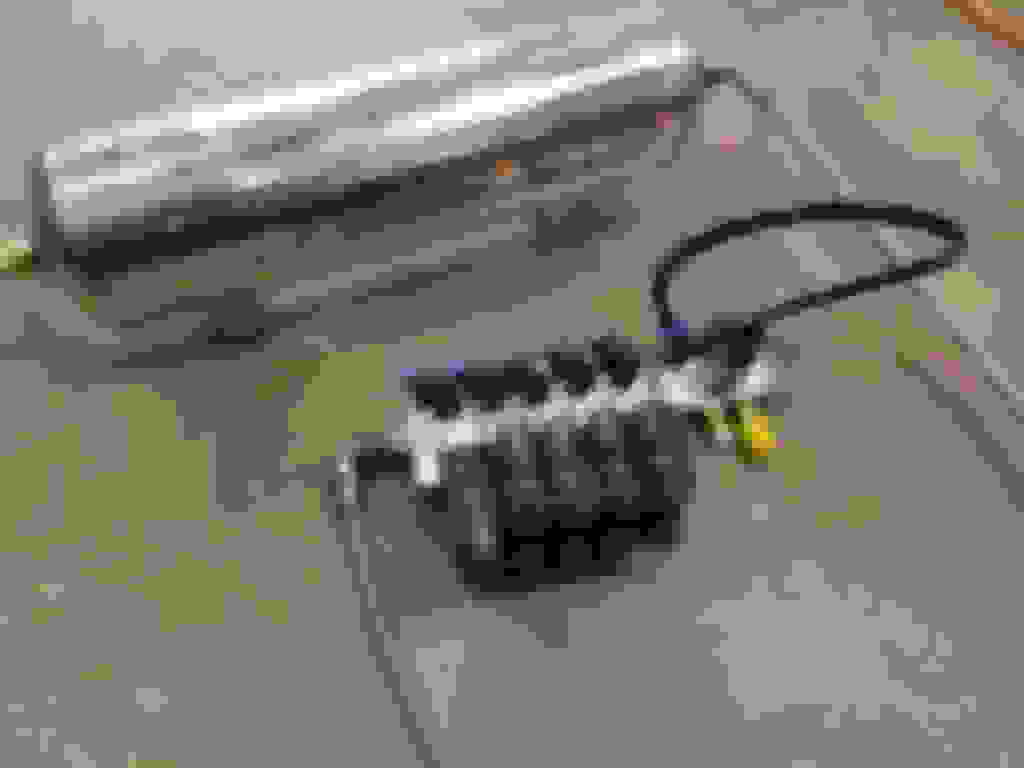
I ordered 2 x 3 position air cylinders and a single cylinder to operate the clutch (not shown). I'll machine up a billet connector so that a second clutch master will directly bolt to the pneumatic cylinder. I'll then run this second clutch master cylinder inline with my existing pressure line just like a hydraulic handbrake setup.
You can see the nice little magnetic sensors on the image above. The LED light turns on when they are in range of the magnetic cylinder ring inside switching the input to the arduino. I have the gear checking code totally separate from the pneumatic code so that I can fire off a shift and then check for achieved gear afterwards. The sensor code also drives the LED display. This way if a shift is not achieved the system will error and won't allow further gear changes without my intervention.
I am using a common manifold to connect all the control valves (2 for each shift direction and 1 for the clutch). Although I just realised I need two more valves to effectively control the 3 position air cylinders without slowing them down. It's so hard to find information on these sorts of cylinders... even the local experts have no idea! Oh well I'll just hang a couple more off one side.
I'm going to run a 4L aluminium tank air tank driven by an ARB 4x4 air pump. It only takes around 15 seconds to build up to 80PSI. The tank gives me a decent buffer of air which should be enough for around 20 -30 shifts without the pump turning on. I'm using more air than a normal pneumatic sequential as I have to run multiple shifts axis to move a single gear position. With a sequential box you just move it up or down.
Most of my time now is in finalising the wiring loom. It's tedious work with now over 24 control inputs / outputs running to various sensors, relays and my ECU. It's all a bit crazy but will be awesome when it's working... if it works!
I have finished the mechanical side with the pneumatics mounted to a cradle that directly push and pull the shifter cables. The gearbox levers system some final trimming and the cable mounting plate needs painting but other than that it is fully functional. I'll loctite everything on final assembly.
The arduino is fairly crazy niw with over 42 wires connecting various sensors and outputs. To fire these 3 position cylinders I need 3 x 2 port valves per cylinder meaning I need 8 valves total with clutch and idle blip control. This all requires some mad coding to fire the required valves to acheive a move. It's all gotten a bit complex but I'm pretty sure its doing the right things and it wirks great on my test bench.
All I need to do now is wire up the valves to the relays and apply some air pressure. I have to be a bit careful though because these air cylinders might have enough grunt to bend shift forks etc if the dogs aren't in alignment. My plan is to hook up an electric drill to drive the input shaft at speed so that the dogs can bounce and engage. I can even run the drill from a relay so that I can test shift cut outside the car.
One more week and I should have a video of it all running.
I'm in risk of this thing becoming vapourware. Nearly 12 months late but here is a quick video of it running on the bench.
I've been busy with work so this thing got shelved for a while. It still needs some tweaking and the whole shift order needs flipping 180 but I can cycle through the gears. In this video it's running at 25 PSI to reduce loading but eventually I'll push it up to full pressure and speed. I' need to sort out the code and start tweaking the timing.
yeah i dont even know where to begin. You are amazing with this stuff. sort it out, then help me set one up for BMW trans/K24 miata. Then Ill have to build that engine just so I can hear it shift at 10K
I think a mechanical sequential would have been easier. There are some difficulties with paddles and pneumatics in that they are basically digital. On or off.
Getting the car to engage 1st or reverse is actually pretty challenging due to the dog teeth. The faces of the dogs are fairly large and flat so if they aren't in the perfect spot they won't mesh. Normally you just put some load on the shifter and gently release the clutch to get the input shaft rotating and when the teeth align it clunks into gear. I'm going to have to find the balance between stalling and launching the car forwards.
In hind sight I should have kept the gear shifter so that I could manually select 1st and R then use sequential when running.
The reason the WRC cars jump fowards when selecting 1st is due to this reason. The clutch never fully disengages so the input shaft is always turning. I have to do something similar.
Wow, nicely done! You could experiment with a bushing instead of a bearing for the pilot bearing. With a little more drag than the bearing it might keep the input shaft turning enough to let the dogs engage properly.
That is ******* amazing. I have just enough experience to know how huge an effort this was but this is so far beyond anything I could do myself.
I don't even think about it before I start... I just dive right in there and learn as I go! If I sat down and thought out all the issues I probably would never attempt it.
I did have another play with the code and I've sorted the shifting order and fixed a few bugs. One thing had me stuck for a while until I realised I was using the same arduino pin for the shift cut and the one of the pneumatic solenoids so it was being turned off by another function. It meant it wasn't quite engaging the gear properly. My code is pretty messy and I as I've added functionality I've made it even worse. Once I know what I'm doing I might just rewrite it from scratch.
The box is cycling up and down through gears smoothly whilst being driven by the drill. When running it I realised I need to change the way I'm shifting out of neutral because one bump of either of the paddles engages a gear. I've accidentally tapped the paddles a few times whilst adjusting something mechanically and those pneumatics pack a punch... plus it's probably not good to engage a gear by accident when in the pits. I'll make it so I need to hold the shift paddle 2 seconds before engaging 1st or Reverse.
The next stage is to bolt it into the car and sort out the CANbus integration, shift cut, startup procedure etc. Based on the bench testing I think I'm at the point I could safely use it to go up through the gears no problem. I've done it a hundred times now without an issue. Stepping down through the gears I will still need to use the clutch, hit the down shift, manually rev match and release the clutch oldschool way until I build something to autoblip. I just need to be confident that the gear shifting works and selects the appropriate gear in order without any chance of a miss-shift. If I get 3rd instead of 5th or even R I could easily end up with destroying a motor or putting the car into the wall.
Shame the cam design got ditched. Few moments on a CNC and we'd all have sequential shifters.
I haven't ditched the mechanical sequential idea... Last week I actually dreamt up a new concept which is even better than my first design with only a single main moving part. The 3D designing of it is pretty complex but is really only the first step. The hard part is getting it to function without issues. I think the new design will work really well as there are less wear surfaces and less overall mechanics. In my head the geometries all work... I think.
Here is another test video showing the shifter cycling up and down gears whist the input shaft is driven by a cordless drill (I have issues with a power drill causing emf through the earth... not sure how to fix it). I've added code that requires a 2 second hold to move it out of neutral either into 1st or R. I have also added the functions that only enable the next gear if the magnetic sensors detect that the pneumatics successfully entered the target gear. If a gear fails to engage, then the shift controller will set the corresponding selector paddle to retry the same gear instead of moving onto the next. This is now all the code implemented that can be tested on the bench. All up it's looking fairly resilient to errors which is good so I think the next stage is to bolt it into the car and sort out the shift cut and CANbus integration.

 06-25-2017, 10:23 PM


 0
0