When you click on links to various merchants on this site and make a purchase, this can result in this site earning a commission. Affiliate programs and affiliations include, but are not limited to, the eBay Partner Network.
Hi, I have a MS3Pnppro from DIYautotune. I am having some difficult conceptualizing wiring the wideband. I have an Innovate LC-2 waiting to be connected. I know that the innovate draws 3 amps during heat up for the heater element and I now know that the lc2 has a combined ground for both the heater element and for the wideband itself. I was planning to run the wideband negative to the megasquirt on the sensor ground port but that looks like it would put too much current through the board and throw off any other sensor on the sensor ground during heat up.
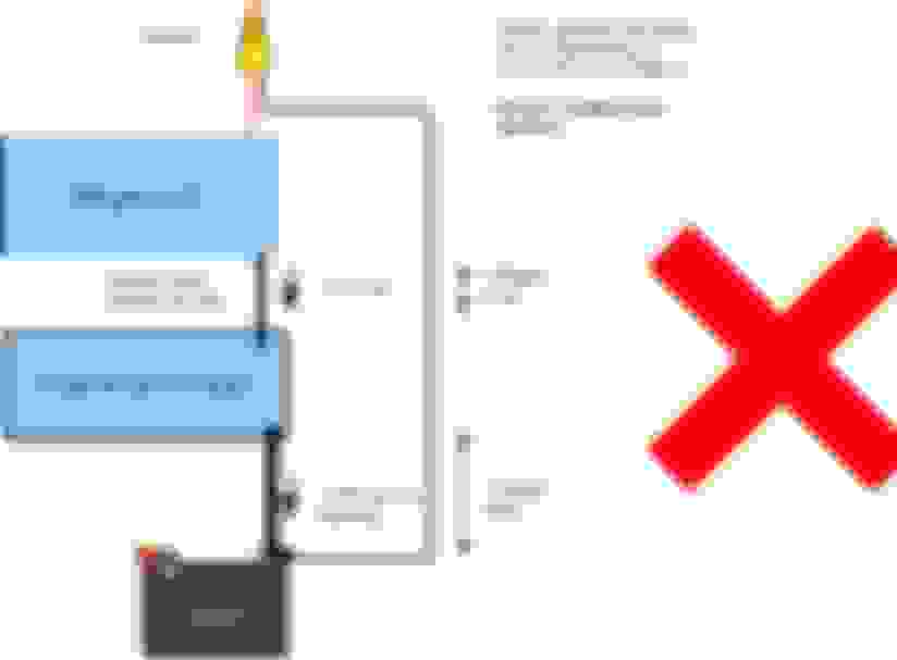
Is my best bet to run the wideband ground straight to the chassis ground? . On the optional connector port 2G on the megasquirt it says ground and not sensor ground. Is that a normal ground that connects to the chassis ground on the head? Is that the port that I should have my wideband connected to? I called DIY and they suggested running the ground directly to the battery but that seems to run counter intuitive to the attached photo that brain drew up.
I feel like I am reading conflicting information. I saw that this picture shows what is and isn't a good idea for these sensors. I want to run the wideband through the megasquirt but I don't know that the ms3pnp physically can accommodate it.
In addition, what is the recommended 12+ switched power? The auxiliary connector says that connector J is a switched 12v but it can only supply .5 amps which seem to power a relay. Am I to assume that optional connector 3L, which says "12v out relay supply" is also limited to the same .5 amps? Tapping off of the room cigar circuit doesn't seem electrically consistent given that on the na6 it is paired with the radio. I read that some people were suggesting running it off of the power window circuit but if I am putting the windows up or down won't that affect the voltage and drop on the gauge and I am not sure which other car components run off of the power window circuit that might be cycling on and off power.
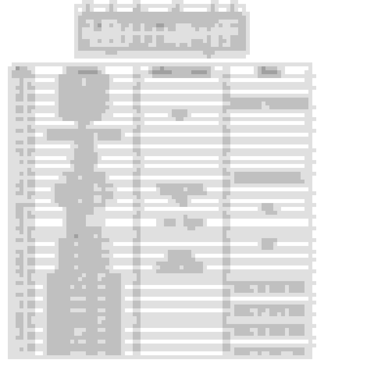
I am planning to run the yellow wire from the wideband controller to the optional connector 2B.
This is what the megasquirt guide says for my particular megasquirt.
Used the same White/RED (+12V) and the same Ground for both MS3x and the Innovate gauge; tapped to the same wires.
I used sensor ground for shielding the output signal wire from the AFR gauge to the MS3x.
I ran an additional heavy gauge (10awg) wire tying all the megasquirt grounds to the chassis.
This eliminated a lot of noise I had. But I still needed a tiny bit of voltage offset to get the two synced correctly.
Used the same White/RED (+12V) and the same Ground for both MS3x and the Innovate gauge; tapped to the same wires.
I used sensor ground for shielding the output signal wire from the AFR gauge to the MS3x. I ran an additional heavy gauge (10awg) wire tying all the megasquirt grounds to the chassis.
This eliminated a lot of noise I had. But I still needed a tiny bit of voltage offset to get the two synced correctly.
If I understand that correct, I could replicate something similar by taking connector 2G and connecting that directly to the chassis ground.
I could probably even use that same chassis ground point to ground the wideband too.
when i set mine up i ran a relay for the power as per wideband manual. and tapped key on off the radio so it turns the relay on. You should ground the wideband to the engine block near the factory ECU ground wire to ensure an accurate reading.But i ran mine to a stud under the dash on the firewall and no problems.Then just run the other wire to the ms and set up you're settings.

 09-10-2018, 11:36 AM


 0
0


