When you click on links to various merchants on this site and make a purchase, this can result in this site earning a commission. Affiliate programs and affiliations include, but are not limited to, the eBay Partner Network.
03+ miatas power the car unlike every miata before its time. The ECU provides a ground to the main relay when the ECU is powered, thus activating the main relay.
Your MS3X must do the same.
You have two options:
1. move the INJ E wire that's used for your CEL light to 3H and change the programmable outputs for INJE to always be on when the ECU is powered.
2. populate an LED circuit on the mainboard, send that output to one of the spare 1-2-3-4 holes on the mainboard to 3H, and change the programmable outputs for that LED to always be on when the ECU is powered.
simply enabling the output with "power on value" to ON, should do the trick. But since you have to use an active condition, you must also set that to ON. then the parameters shouldn't matter.
Great explanation, thanks. Populating the LED circuit sounds like the lesser of two evils since I'd like to be able to have my CEL programmable if something is wrong. You mentioned if I was running the knock module (This one right? https://www.diyautotune.com/product/...ck-module-kit/) I couldn't do that. I was planning on potentially getting it in the future, what was the other option you mentioned?
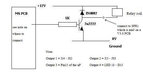
I would use Js2 to the 1K (should equate to IAC2 on the above screen). then SPARE 1 to 3H. you can recycle one of the transistors that would have been used for the LEDs or Q2/Q4. (the higher amperage one here is probably the best).
I would use Js2 to the 1K (should equate to IAC2 on the above screen). then SPARE 1 to 3H. you can recycle one of the transistors that would have been used for the LEDs or Q2/Q4. (the higher amperage one here is probably the best).
Just to summarize what I've done before I plug it in:
Using the above schematic I've made these connections-
yes, but how did you wire the 12v? did you actually go out to the harness for it? otherwise, the main relay is already connected to 12v...
to elaborate: you're not wiring up 12v, you're just sending your flyback diode to 12v. we typically use s19 for that (same spot you use for the flyback mod on the expander)
Yes I went to the harness for +12V by running a wire from the banded end of my diode to (MS-12/ 4H) but I'll change that to go to "S19" depending on your answer.
I was a quitter and decided to just use my CEL instead. Works like a charm. Finally getting this thing to run is amazing. Thank all of you who have helped me get this far. Something I'm stumbling on is I'm not getting any manifold pressure reading in TS. Technically it's reading something but it's just showing 100kpa (atmosphere) I understand our cars have a MAF and not a MAP, but what actually tells the MS3X my manifold pressure? I saw people mention having a GM IAT has something to do with not needing a MAP, (which I have installed) but my VE tables only move horizontally even though my manifold pressure is under vacuum.
Technically it's reading something but it's just showing 100kpa (atmosphere) I understand our cars have a MAF and not a MAP, but what actually tells the MS3X my manifold pressure?
MAP sensor is built in to the MS3X. You need to connect a vacuum line to it.
MAP sensor is built in to the MS3X. You need to connect a vacuum line to it.
So it does use the built in one. Just noticed the trubokitty guide says "The DB37 connector must be installed before the MAP sensor, so I like to get them out of the way." but it never inherently says to ever install it after that. I missed that part since it was like the first build step. Also: RIP DB37 20xx-2018
03+ miatas power the car unlike every miata before its time. The ECU provides a ground to the main relay when the ECU is powered, thus activating the main relay.
Your MS3X must do the same.
You have two options:
1. move the INJ E wire that's used for your CEL light to 3H and change the programmable outputs for INJE to always be on when the ECU is powered.
2. populate an LED circuit on the mainboard, send that output to one of the spare 1-2-3-4 holes on the mainboard to 3H, and change the programmable outputs for that LED to always be on when the ECU is powered.
simply enabling the output with "power on value" to ON, should do the trick. But since you have to use an active condition, you must also set that to ON. then the parameters shouldn't matter.
So while this DOES work, while cranking my main relay seems to flicker on and off until it sputters to life. Once it's on it's solid, but I'm thinking it may have something to do with my 12V source? It sounds like that one dude trying to start a 76' Chevy Vega running on purely faith

 06-24-2018, 08:14 AM


 0
0


 status on my profile.


