When you click on links to various merchants on this site and make a purchase, this can result in this site earning a commission. Affiliate programs and affiliations include, but are not limited to, the eBay Partner Network.
Ok, so I've had a hard time finding the pin outs for wiring the db37 connector and factory ECU plugs... mostly cause a lot of the links and pictures are old and no longer work. Sorry if they are still live somewhere but I found these via some google searching and help from the guy who sold me the MS:
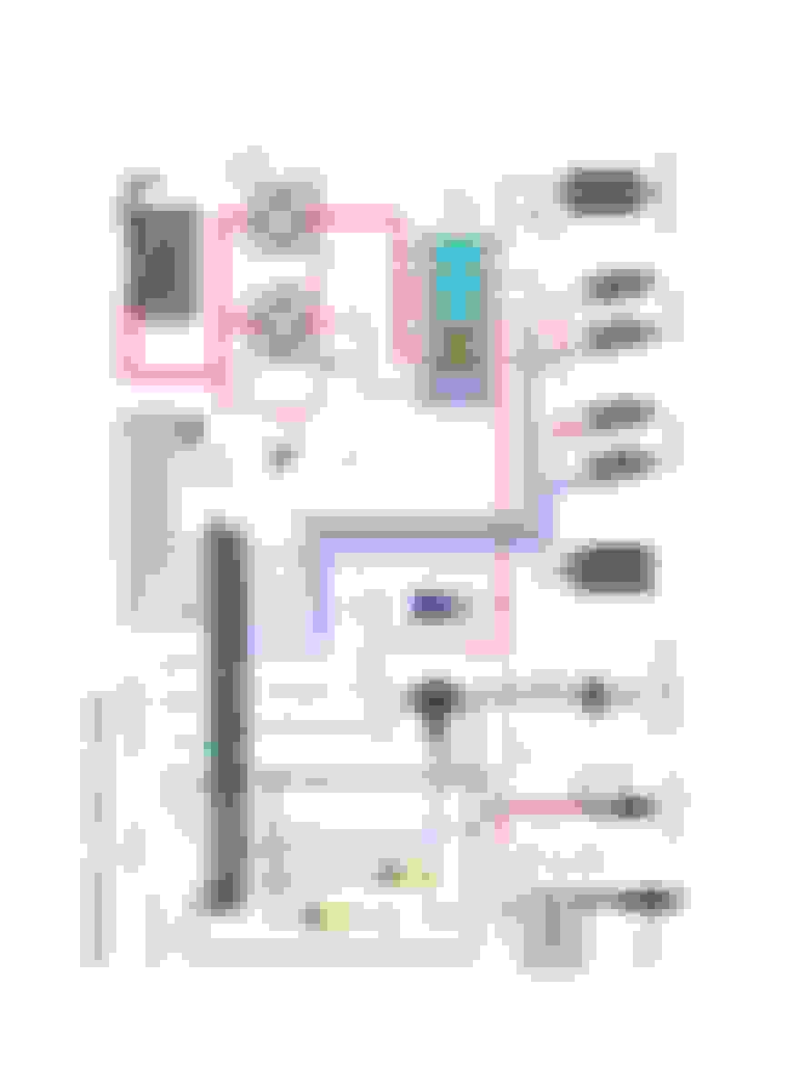
BUT my question is on the pin out for the ECU connector, they are not labeled and I want to make double sure I got it right.
Hopefully that picture isn't too garbage...
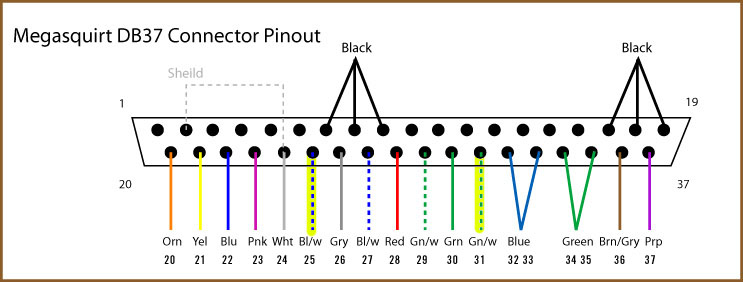
I ordered the DIY auto tune cable bundle (so glad i did, other wise they would have all been red, black, or green) and I've already wired the db37 EXCEPT for the shielded cable. Again double checking: the black wire goes to pin 1 and the white goes to pin 24. and the bare wires (shield ground?) go to pin 2?
Any who, I'll finish that up tonight (hopefully) and then all I'll have to do is install/wire the wideband, IAT sensor, and variable TSP (mustang). I'll have to check that stuff out tonight as far as wiring goes. I've already checked out some wide band info but zero on the tps and temp sensor. I wasn't expecting to but I may even get this thing on MS this weekend...
I got the db37 100% done, tested, and heatshrinked. On the ecu plug I'm kinda worried alot of it isn't used. Also, the two blue and two green lines for the injectors could have been jumped on the db37 instead of wiring them together. I've got everything preped (wires and post tinned) just gotta throw it together.
I'm gonna keep the factory cross over tube for now and ditch the factory maf-filter-thing and throw a cone filter on the end. I'll likely install the air temp sensor temporarily into the last plastic piece (the one connected to the throttle body). The lambda controller I'll likely put under the kick panel with the MS.
I got the db37 100% done, tested, and heatshrinked. On the ecu plug I'm kinda worried alot of it isn't used. Also, the two blue and two green lines for the injectors could have been jumped on the db37 instead of wiring them together. I've got everything preped (wires and post tinned) just gotta throw it together.
I mean you could ask some of us here with over ten years experience building and modifying MS units... well, we also all would have discouraged you from a ms2 cpu as well...
Oh don't worry, I will definitely post up my share of questions. I generally enjoy researching topics that interest me. I find myself reading through threads where people are having issues I don't even have... from the early 2000s. My biggest problem is not knowing what questions to ask, like unforseen issues I haven't encountered yet.
Like the idle valve under the throttle body... I never really noticed the hose coming up and tying into the air intake. But I researched installing IC piping and saw where most people just tie it into the closest hard pipe. (Saw something about installing a check valve to prevent boost leaks but I have to check into that more).
TLDR I try to answer as many questions myself as possible.
And on the MS2... I got it for $350 with a variable tps, Toyota coil plug adapters AND it has been modified for sequential injection (though I won't be using that for a while). For the price I'm more than happy, I was gonna go DIY but for the money I couldn't pass it up.
So i havent have much time to finish the "PnP harness" (pregnant wife so doing all my soldering while shes at work... aka one day). So here is me asking people with over ten years experience for help
I have several wires left that are showing wired on the db37 "schematic" but not on the ECU connector.
I have left: purple "ms-37 fuel pump" wired to pin 37
tan, tan-red, tan-orange, tan-green "ms-3 spr1/2/3/4" wired to pins 3, 4 , 5 , 6 respectively
black white no label to pin 7
blue-red "ms-27 iac1a" to pin 28
and the shielded wire (for the cas i believe) black to pin 1, shield (bare) wire to pin 2, and white to pin 24
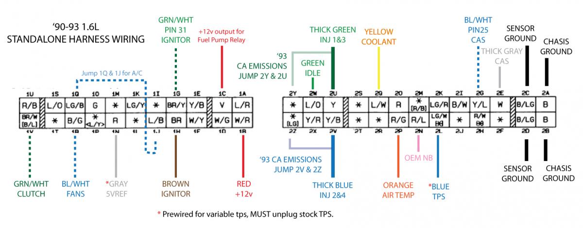
I have searched all over and I'm finding it difficult to locate the specific info, when I do think I found it the links are dead. I see where it says "thick grey" to pin 2E but im not 100% sure what that mean. I assume the white wire and then the black and shield go to ground. That's just "***-u-me'ing" though.
pins 3456: you have nothing connected to the spares, so those wires are just going to dangle on your harness... pin 7: this is the crank input -- this should go to "thick gray cas" pin 25: this is the cam input -- just use the matching IACXX wire for this, you don't need a shielded wire.
I have a helpful db37 diagram for you that's specific to my harness diagram your using, I just cant access it at work.
MS2 units are very old, and require lots of hand building circuits to make them work. even the MS3 is old at 8 years now, and requires nothing custom to make it work on a miata.
I appreciate the input sir. I'd like a look at your db37 diagram when you get the time to post it... its supposed to rain all day today so I wont be installing it today anyways.
I bought the DIYAutoTune wire bundle which comes with a shielded cable. It was dirt cheap considering the labels and color coded wires. If i had just used what I had on hand all the wires would have been red, green, or black.
I bought the MS2 from another member here. He ran it in his car for a while so I should be ok on MS2 mods. "Should be". Supposedly it was modified for sequential spark but for my power goal I dont see me fiddling with that for a while.
So I still have pin 24, 27, 1, 2, and 37 going to nothing... on the ecu connector nothing is going to "blue/white fan". Definitely got something wrong some where
I found it via google. didn't have it hosted anywhere still:
Ok, i see the "shield" is wired to pin 2 and the white goes to pin 24 the black wire that is in the shielded cable just go to one of the six other grounds? (then to sensor ground on ecu plug?)
Originally Posted by Braineack
Where pin does this extra red "fuel pump" wire go to? All i see is the red 12v (pin 28)
Originally Posted by Braineack
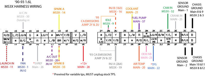
preferably, you'd build two circuits:
(1) input on 1Q so bring the a/c switch into the MS,
(2) output on 1J to allow the MS to activate the a/c using the a/c idle up code.
I will look and see if my unit has them already and post up some pics. We'll go from there.
Originally Posted by Braineack
also, put fuel pump on 2O and jump that pin to the fuel pump relay via your AFM connector:

 05-09-2018, 07:03 PM


 0
0


 It will not go unnoticed sir, thank you!


