When you click on links to various merchants on this site and make a purchase, this can result in this site earning a commission. Affiliate programs and affiliations include, but are not limited to, the eBay Partner Network.
Reaching out for some suggestions. I am closing in on finishing up installing a TSE EFR kit in my '96 (hope this is the right section). Finally getting to building some charge piping. After clocking the turbo and having a actual look at what could work, I am realizing the limitations of pop up head lights. Anyone would care to share their ideas/success/failures of running charge pipe for this turbo/mani and chassis or similar. I am initially planning on keeping the AC and PS in place. Not seeing a whole lot of threads out there address the issues, maybe i'm looking wrong... Its seems at this point i'll need to employ a fairly convoluted plumbing system to get this working; maybe a 180* right off the compressor outlet, seems less than ideal. or go through the wheel well which seems like a worse idea.
2 inch piping on the hot side. Check out the routing for Lars’ complete MKTurbo kit; he actually has the turbo clocked towards the hood, then the piping taking a 180 degree turn down to get it in front of all the PS/AC stuff.
3x aluminum bends. One 90deg, one 60deg, one 45deg. These will be welded together. The idea is to get behind the swaybar, then wrap up and around it from behind. The 45deg bend is last in the sequence, and the piping comes up between the alternator, frame rail, and sway bar. The 90deg and 60deg can swap places depending on the exact path you take. Tuck it as tight as you can to the pulleys to leave clearance for fans.
90deg 2.5" to 2.5" (OEM TB) or 2.75" (Skunk2 TB) coupler into throttle body
The only other secret is to keep all the piping inboard of the sway bar on either side. That ensures clearance for the wheel/tire at full lock.
Before I could weld, I would fit all the pipes with 2" painters tape, then transport to a welder for tacking and welding. To trim/adjust silicone couplers, use a hose clamp as a guide and a brand new razorblade in a box knife. Fresh blades go through silicone like butter, and the guide makes the cut foolproof.
Beadroll both pipes when you're done and use good stainless worm-drive clamps.
Oh man, a definitive answer indeed! thank you sir. I will be ordering up some pipe bends tonight, this is a big help. When it comes to welding this thing up it should be interesting, a friend will keep me on the straight an narrow but I hope build it without assistance. appreciate the advice.
Cold side, you can do it with three 2.5" 90* couplers, and a 45* aluminum bend. 90 out of the intercooler pointing toward the back of the car, 45* aluminum pipe parallell to the ground and pointing toward the driver side. This will get you inboard of the sway bar and under it, as well as directly down from the throttle body. Then a 90* coupler pointing directly up, staight piece of pipe and a 90 into the throttle body.
Just FYI what works on one set of years won't necessarily work on other set of years. IE IC pipes are specific 90-93, 94-97, 99/00, and 01-05. The different AC and PS line layouts through out the years really throw kinks in making universal pipes. Larger swaybars and radiators and fans can also cause issues.
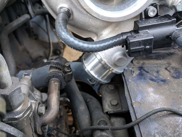
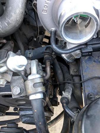
Here are a couple of pics of a vertical outlet. Obviously, Sav's suggestions are probably the best method. The first two (erlier version) have a custom 2" bend, the third (final version) is a standard 90 alum cut short with a 90 deg coupler. I don't seem to have any handy of the hotside intercooler piping. I never liked the 180 or tight 90 on this setup, but I didn't notice any obvious performance issues.
Jeez guys some awesome suggestions. Love all the photos. I think Savington makes the most sense from a volume reduction stand point. While I also agree with schrodinger that Hornetball sure has a clean setup. Probably easier for me to build as well. I ordered enough bends to go either way. Likely I'll aim to go for the Sav's suggestion and falling back to the routing path hornetball used if i am having any clearance issues. You all might be disappointed but I am going with alumizined mild steel as a material, mainly for ease of welding. Is brazing aluminum strong enough for this application? I guess its something that's pretty easy to change if my skillset and tool set progresses
As for aluminum brazing, it's plenty strong. I really do DD mine and have more than 70K miles with the turbo on it.
Not only is aluminum light, but it's really convenient to order the bends you need from Aluminum Pipes and similar vendors. That said, I've seen a few people use steel for their intakes -- it works.
Steel works, aluminum is better in every way. Even if you can't weld it, it's still worthwhile to mock them up in aluminum and then have them welded elsewhere.
yeah, the shame! I get it though, certainly a reason Aluminum is the standard. Since this is shaping into a little learning project for me i'll likely have a go at it with steel to get started. No doubt I'll want to change it 6 months out... but getting in the experience is important to me.
90deg 2.5" to 2.5" (OEM TB) or 2.75" (Skunk2 TB) coupler into throttle body
I'm running a 120* out my skunk2 TB almost straight down, slightly towards the passenger side outside, so it clears my fans and sway bar, then a 90*, 90*, to my IC
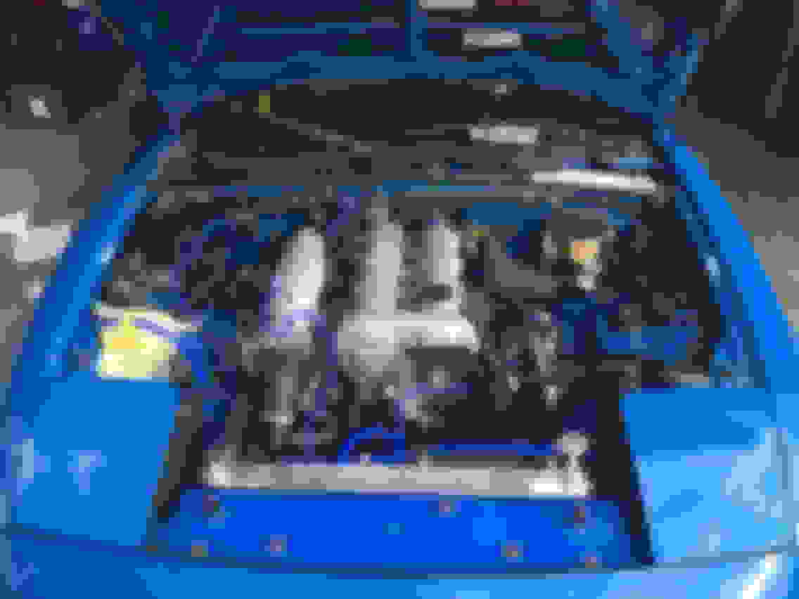
Got some pipe bends and straights in and took the opportunity yesterday to workout the suggestions presented. I am not seeing any possible way to route this with the compressor outlet pointed down without major rework of the PS reservoir location and likely ac compressor removal. There is just no room. Even with the 2" pipe, it's so tight in there. Looks like most that have posted here have done modifications to accommodate this orientation of the outlet. At this point, for the hot side, looks like plan B is a go, which will be following hornetballs technique bringing behind the fender. Here is a look at the layout I'm working with. Just an update for anyone paying attention.

 04-10-2018, 08:12 PM


 0
0