When you click on links to various merchants on this site and make a purchase, this can result in this site earning a commission. Affiliate programs and affiliations include, but are not limited to, the eBay Partner Network.
Not exactly, because I have an MS2, but let me walk you through my logic. The new 3" exhaust system I'll be installing utilizes a test pipe instead of a catalytic converter. I'd love to be able to pass the smog test without a cat, and I think my chances will be higher if I keep the EGR. If not, I guess I can always replace the test pipe with a Magnaflow 59559, but it would be nice if I can avoid that. Is that realistic?
I've also read that deleting the EGR doesn't result in performance gains, so if the only advantage is saving $50 on the fittings, I'm fine keeping it. If there are other benefits I'm not aware of, I'd be interested in learning about them.
The other benefit is not running your engines *** juices back into its mouth human centipede style. You also won't be passing a smog test without a catalytic converter. OEM's can't do it. What makes you think you can?
Totally off topic but this song uses sound samples from Windows 95
Thanks. If I ever make a post-install video, I'm definitely using this for the background music.
Originally Posted by SpartanSV
The other benefit is not running your engines *** juices back into its mouth human centipede style. You also won't be passing a smog test without a catalytic converter. OEM's can't do it. What makes you think you can?
Solid visual on that EGR metaphor. I don't have a strong basis for passing the sniff test on a catless system other than reading about a few others who claim to have done so on a good tune. I'm not against adding a cat. I'm mostly just curious if it's possible.
Currently in the process of installing the water bypass system from BEGi. I removed the power steering pump so I could remove the OEM water inlet flange and the pipe that goes back to the heater hose.
I put on a fresh gasket on and began bolting up the new flange with the existing 12mm bolts. Top bolt went on fine but the bottom one didn't tighten all the way. Since the bolts are steel and the outlet flange on the water pump is aluminum I didn't want to force it. So I pulled out the bolt and noticed some shavings on the threads, so I think the hole on the pump's flange is stripped. What would you do?
Epoxy on the bolt since it's not a high torque application
Helicoil on the pump's flange
Replace the timing belt and water pump while I'm at it
I would replace the water pump. Trying to repair the threads there would suck without pulling the pump, and once it's removed you might as well just replace it.
I would replace the water pump. Trying to repair the threads there would suck without pulling the pump, and once it's removed you might as well just replace it.
I knew that would be the answer, but I'm really not looking forward to the labor involved. The engine has 130k and I don't know the history so timing belt and seals are probably in order as well.
Finally getting around to this. I will be replacing the timing belt, water pump, front crank seal, cam seals, valve cover gasket, tensioner and idler pulleys, camshaft angle sensor (CAS) seal, and thermostat outlet seal. I have a couple questions while I have everything apart.
For those of you with Proteg�/Escort/Tracer valve covers, where did you relocate the breather tube? It looks like I can drill a 5/16" pilot hole and insert the tube just about anywhere on the valve cover. I've seen someone put it on the passenger side of the valve cover behind the PCV and run a tiny filter straight off the tube.
Any tips on mounting the coil pack bracket? The current plan is to tap the rear breather tube hole so I can stick a bolt in there for a homemade bracket
What is your opinion on adjustable cam gears? I am replacing the cam seals so I figured now would be the time to replace them if it's worth it. If OEM, has anyone powder coated them for sick club roadster style points?
For those of you with Proteg�/Escort/Tracer valve covers, where did you relocate the breather tube? It looks like I can drill a 5/16" pilot hole and insert the tube just about anywhere on the valve cover. I've seen someone put it on the passenger side of the valve cover behind the PCV and run a tiny filter straight off the tube.
I ended up tapping a 1/8" NPT hole on the valve cover. Who knew this would require an R-size bit for the pilot hole? Not me. Anyhow this allowed me to thread on a 1/8" NPT to 3/8" hose barb adapter which accommodated a tiny Spectre 9mm filter. Photos below.
Brass adapter threaded on
Mini cone filter shown (before installing hose clamp)
To plug the rear I tapped an m10x1.25 hole and put on a fine threaded flange bolt.
Finally getting around to this. I will be replacing the timing belt, water pump, front crank seal, cam seals, valve cover gasket, tensioner and idler pulleys, camshaft angle sensor (CAS) seal, and thermostat outlet seal. I have a couple questions while I have everything apart.
Any tips on mounting the coil pack bracket? The current plan is to tap the rear breather tube hole so I can stick a bolt in there for a homemade bracket
UPDATE: Timing belt, water pump, front crank seal, tensioner/idler pulleys, tensioner spring, cam seals, and CAS o-ring are done. I didn't do the thermostat seal because I'll probably do the coolant reroute in the near future. I also haven't bolted the valve cover back on because I'm not sure if I want to keep the OEM coil pack or install a COP kit.
Anyone running a Toyota/fab9/LSx COP kit with a similar setup to mine? Yay or nay?
Originally Posted by Windows95
What is your opinion on adjustable cam gears? I am replacing the cam seals so I figured now would be the time to replace them if it's worth it. If OEM, has anyone powder coated them for sick club roadster style points?
I found a set of fidanza gears and threw em on. See below.
I also haven't bolted the valve cover back on because I'm not sure if I want to keep the OEM coil pack or install a COP kit.
Anyone running a Toyota/fab9/LSx COP kit with a similar setup to mine? Yay or nay?
I ended up going with the COP kit from Fab9. After installing those (super easy) I bolted the valve cover with the bolts in the right order and to the correct torque spec range (43 - 78 INCH/lbs.) I put em around 60.
Next, I removed the plug in my oil pan and went to replace it with a 90� 1/2" NPT to -8AN fitting so I could connect the stainless drain line. Unfortunately the A/C compressor mounting bracket was preventing me from rotating the fitting clockwise to tighten it, so I had to remove it. This was a pain because I had already reinstalled my P/S pump and belt after doing the timing belt and it's never fun to go backwards when things should be progressing. Here's how it looks.
Oil pad drain line
Here's how it looks with the turbo mounted:
Turbo mounted to exhaust manifold
Next up is installing the intercooler and piping. Getting close!
lol that's the most idiotic location I've ever seen
hornetball explained he did it that way because his car has A/C
Originally Posted by 18psi
if you don't have ac why wouldn't you drill in the traditional spot? its also really easy to access. just seems really weird and silly
hornetball explained we both have A/C so we did it that way
Originally Posted by 18psi
this guy looks like he has ac too, so there's a belt there, and the drain now has to go around all that
I put a 90 degree so the drain wouldn't have to go around all that
Originally Posted by 18psi
that 90 on the oil drain line is really really terrible
I'm not sure what I expected.
Look, if I did it again I might have the A/C discharged, remove the hoses and compressor bracket, and drill the side facing the driver side fender the conventional way. But I didn't do that, so I'm working with what I got. If it doesn't work out, I'm documenting the build so me and anyone who reads it can learn from my mistake. If it does, then at least we'll know there's one other dumb way to do it.
The unconventional routing continues. Here's how I ran my coolant lines to/from the turbo and how I re-routed the heater core hose�the one that used to be the hardline mounted on the exhaust side of the block. I actually re-used the 1.25" steel elbow and had a buddy weld a 3/8" NPT bung so I could attach a 5/8" hose barb to connect the heater core hose. Pics below.
I could use some help figuring out how to connect all my air lines.
I've labeled them below
A - Signal source fitting 1: Boost gauge
B - Signal source fitting 2: Blow off valve (H)
C - Signal source fitting 3: Cruise control
D - Intake manifold: Cold side of intercooler piping (G)
E - Wastegate actuator: ???
F - Air intake: Plug it off
G - Intercooler pipe, cold side: Intake manifold (D)
H - BOV: Signal source fitting 2 (B)
Am I on the right track?
I have an electronic boost control (EBC) solenoid that I haven't installed. If I were to install it, it looks like I would connect the single side (2) to the wastegate and the lower port of the double side (1) to a boost source aka anywhere between the turbo and the throttle body, (G) for example.
Next up is finding a good location for the IAT sensor. I was going to put it on the end tank of the intercooler cold side, but as you can see the A/C condenser isn't going to allow enough room to fit the pigtail connection so I ended up plugging it.
I have a steel bung that could be welded into the pipe nearest to the outlet, but if there are other suggestions that don't involve welding, I'm all ears!
Yeah I couldn't think of a better idea either. I added a couple coats of flat black primer before installing. You can see the new IAT bung just below the IACV hose port.
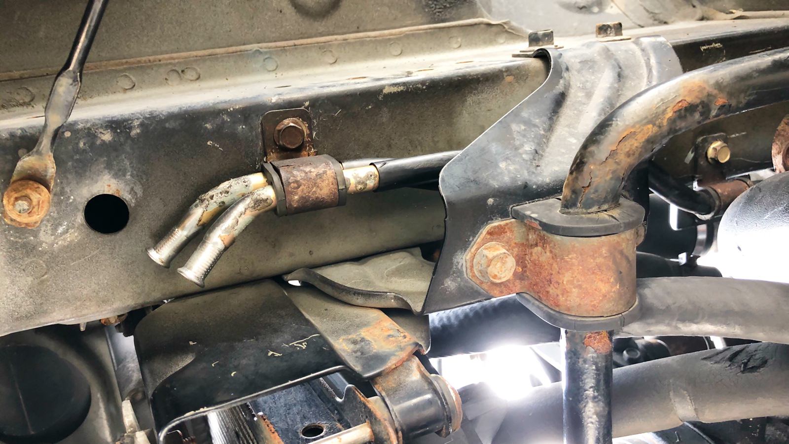
When I first tried mounting the intercooler, the stock power steering "cooler" was blocking it. The stock cooler is basically just a hard line that makes a U-turn in front of the radiator. The shape reminds me of the heating element on an oven. Anyway that thing was preventing the FMIC from going in all the way so I cut the lines, flared on the end, and ran rubber hoses to a cheap accessory cooler. I zip tied the new cooler through the A/C condenser and onto the radiator.
P/S hard lines - cut and flared
cheap accessory cooler
Cooler fastened to the A/C condenser
Rubber hoses routed to accomodate the intercooler
Last edited by Windows95; 04-15-2018 at 04:12 PM.
Reason: images weren't loading

 04-23-2017 | 01:31 AM


 0
0


 P/S hard lines - cut and flared
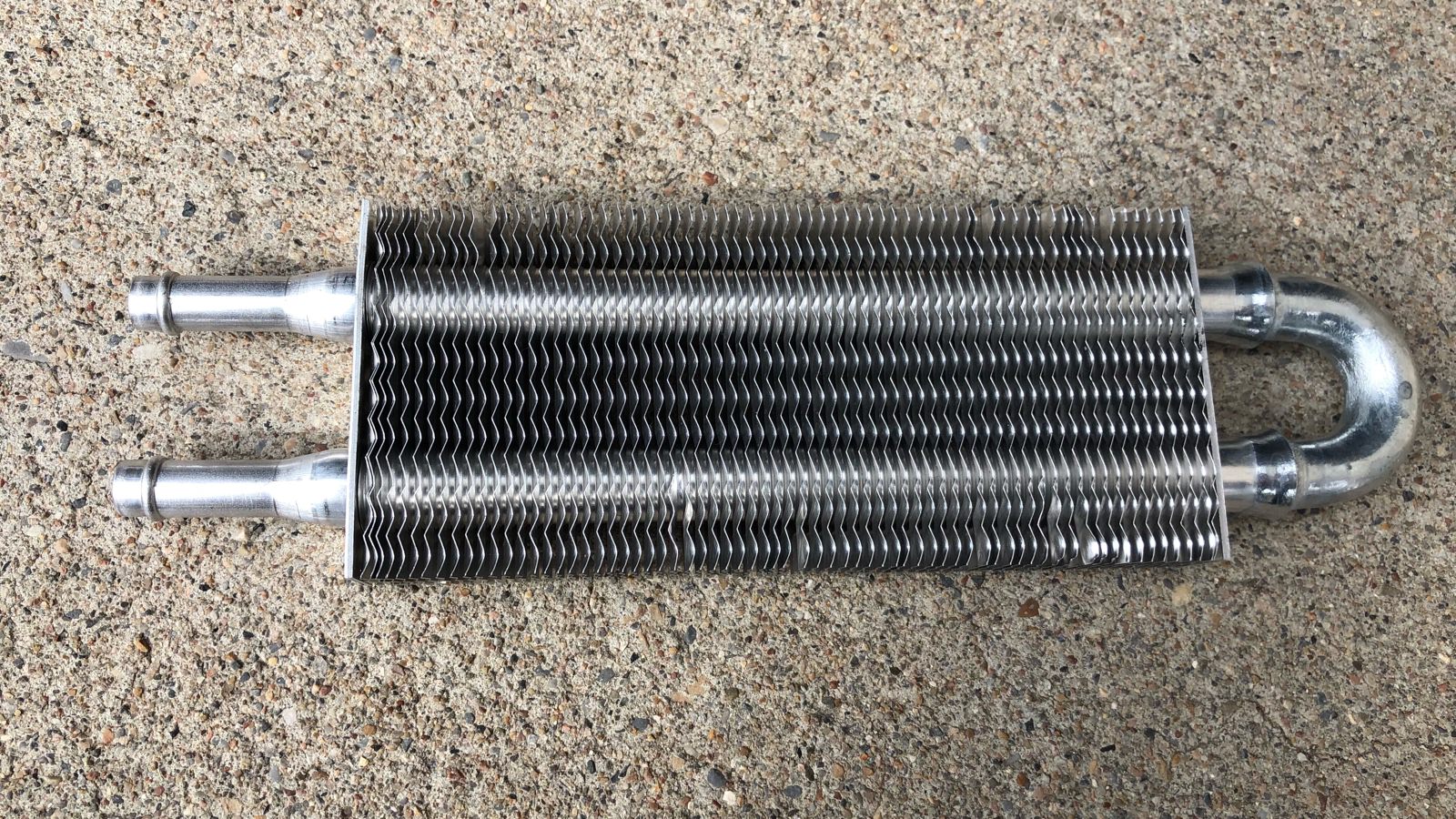 cheap accessory cooler
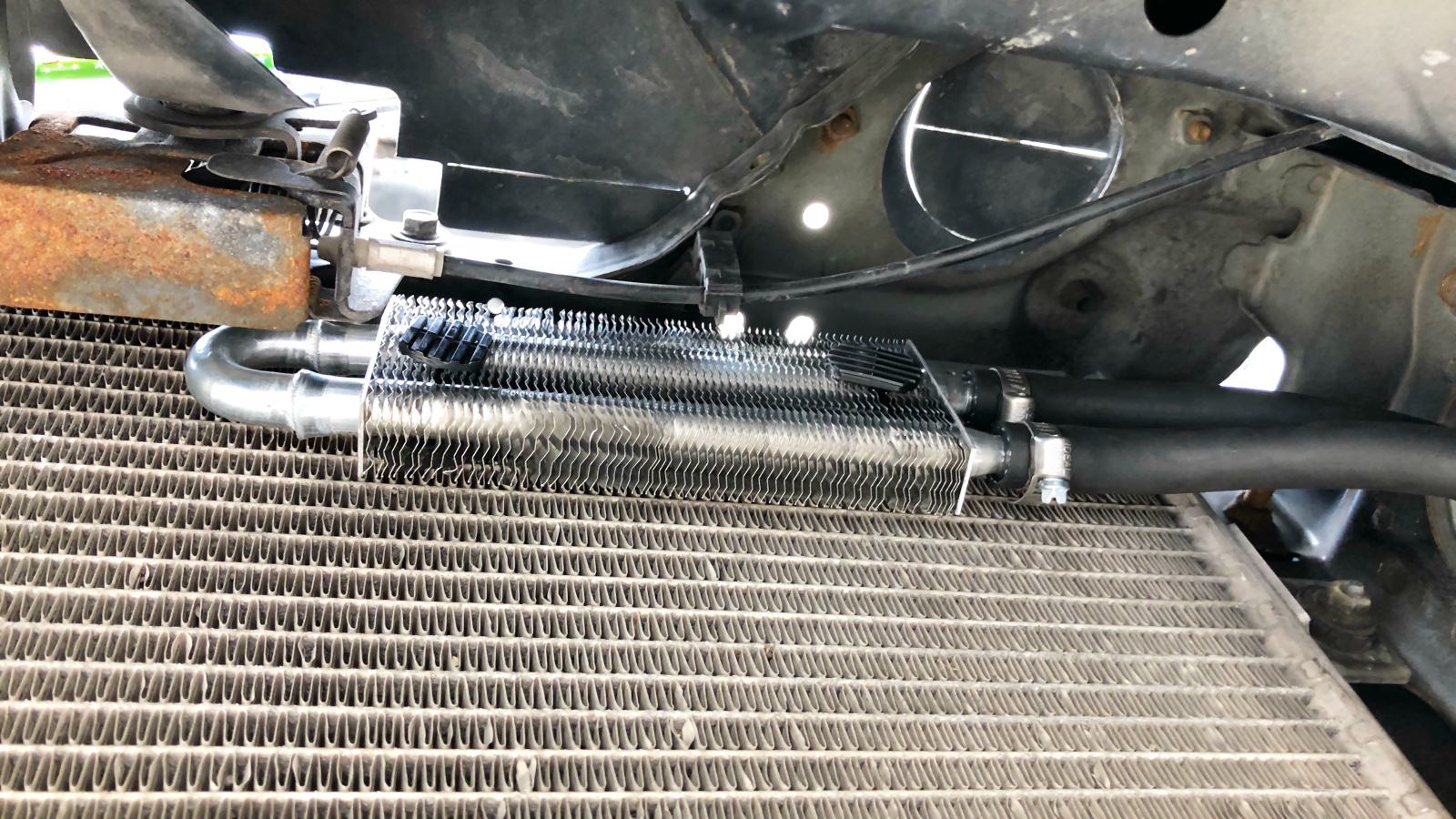 Cooler fastened to the A/C condenser
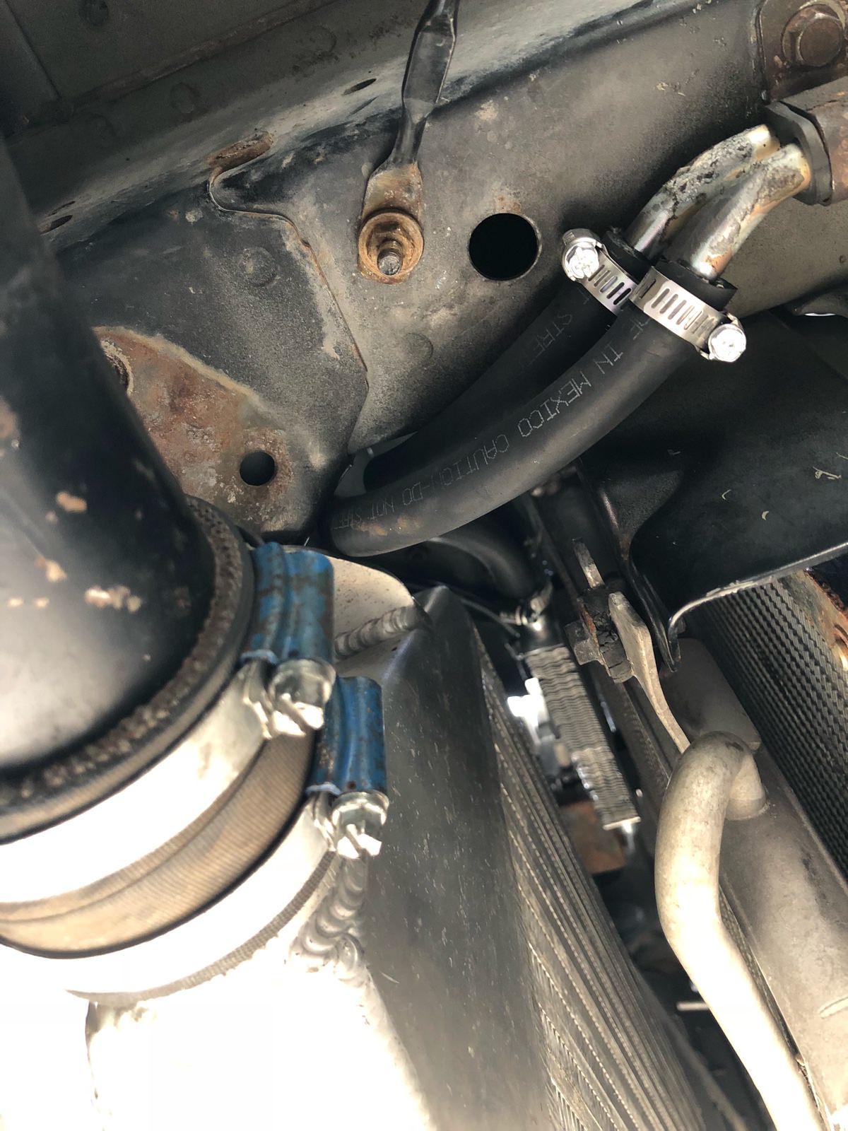 Rubber hoses routed to accomodate the intercooler


