When you click on links to various merchants on this site and make a purchase, this can result in this site earning a commission. Affiliate programs and affiliations include, but are not limited to, the eBay Partner Network.
So I tried to follow the shopping list on trubokitty but apparently I messed up on the wiring stuff. I ordered https://www.diyautotune.com/product/...gtail-harness/ this instead of the wiring bundle (for both this and the ms3x harness). I assumed everything would line up, but when I went to do the grounds on my oem ecu connector I found the extra grounds and decided to investigate. I took the db37 connector housing off to try to figure out which one was which (there are five on this harness, 6 if you count the one in the twisted pair with the crank signal wire, but only 4 in the guide) and I found that this thing is pretty different from what is in trubokitty. The grounds are in 15-19, 5 is the knock sensor wire which is correct, 1 is a ground that goes with the crank sensor wire which is correct, then 2 3 4 6 and 7 are all different. I believe they're unused, but I have no idea what to do next. Can i leave the grounds where they are and still connect everything the same and have it work? I'm assuming no.. I could just use the other wires since they're unused anyways but pin 8 is empty and I can't see how to add or remove wires from this connector so that's no good either..
Am I going to have to cut this connector off and put a new one on? I don't even see how to take this off without cutting, the black plastic is about 1/4" longer than the empty one that I have here, so I can't see the pins or how to remove the wires. Is it fine how it is if I make some sort of adjustment somewhere else? What exactly would that adjustment be?
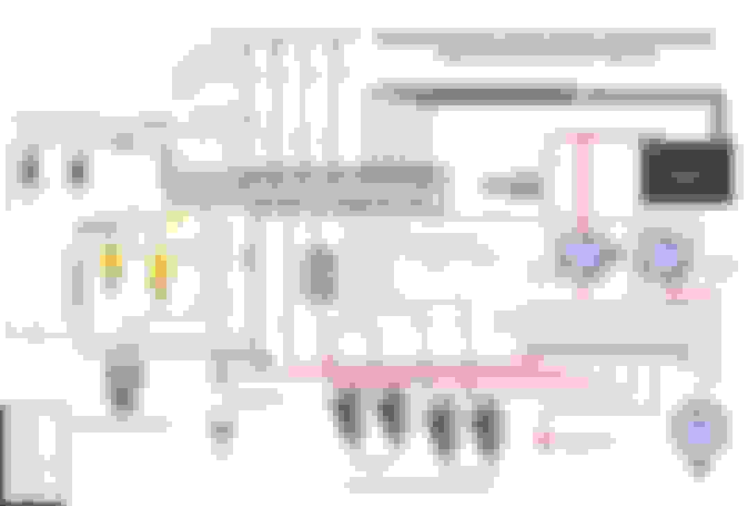
The diagram from the product page on diy auto tune:
and here is what the guide says it should look like:
I realize this is noobish, but I'm just not clear on how all of this comes together yet honestly.

 12-29-2017, 08:51 PM


 0
0


