When you click on links to various merchants on this site and make a purchase, this can result in this site earning a commission. Affiliate programs and affiliations include, but are not limited to, the eBay Partner Network.
I searched through every thread and resource in order to answer my questions, but they all come up short as far as my specific setup. (pls no bully)
The most helpful pages were these:
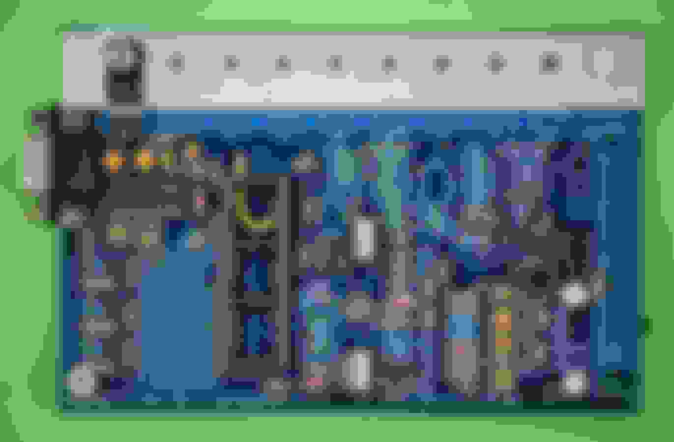
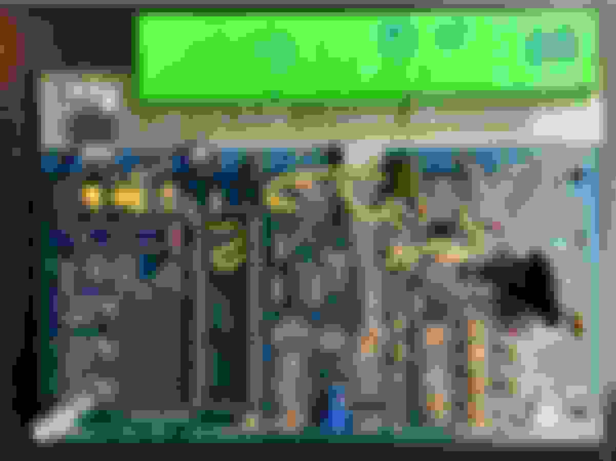
Now as to some background of what I am struggling with. I bought this MS3 kit 2 years ago without a whole lot of research. I would have gone PNP if I had known better.
I currently have a 97 that I am planning to turbo in a few months once I gather enough parts. I'm going to build and install the megasquirt system before I do this in order to get familiar with it, something you guys suggested.
I am confused as to what jumpers and mods I will need to perform on this board. It is my understanding that any V3 board, whether it be MS1, MS2, or MS3, aside from the MS3X (which this isn't right?), needs the same jumper job performed. Correct me if i'm wrong.
I am planning to run the wasted spark FAB9 COP system. I won't bother with sequential ignition for now unless that somehow saves me from having to do some of these mods to the board.
I am planning to run sequential injection.
I will not be keeping the stock ECU, only the harness-side connector.
Won't be running AC (for now).
Mechanical boost control.
Planning on running a UEGO wideband.
If you guys could point me to the right setup for modifying this board, it would be much appreciated. I'm in over my head and feel stupid for having to make a thread. Forgive me, but i'm at my wits end right now.
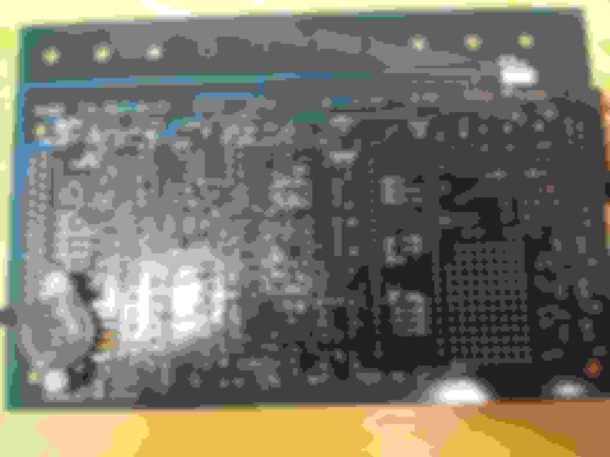
(Yes, I know the LED's are oriented incorrectly. I'm not done with the board yet as you might have guessed from the pictures. I didn't want to accidentally kill the board from some noob mistake without consulting you guys first before I power it on.)
Both of these are dealing with the same V3 Board, but Braineack was using an MS1 processor and Frank was using an MS3 processor WITH the Extra board, which as I have stated before I don't have or intend to use unless absolutely necessary.
But his board had weird stuff like ignition inverters, which I didn't think you needed except under special circumstances, according to Braineack in the thread linked above.
He also retained the MOSFET on the rightmost spot of the heatsink, which from what I can tell can be used for like 4 different mods depending on what you are doing.
I mean seriously. One dude will have 1/4 of the components missing on THIS side of the board and another will have 1/4 of the components missing on the OTHER side of the board, and people will say "yup thats correct!".
Correct according to what exactly? This is some voodoo **** that appears to just be passed down from thread to thread and build to build with nobody having real understanding of the boards except a few guys who came up with the "mods" in the first place.
why would you even consider looking at MS1 documents from 2006 to build your MS3 that was released in 2010 -- especially when hlaf the pictures don't work and the first thing it says is: NOTE: THESE DOCUMENTS ARE VERY OLD AND OUTDATED?
Well I wasn't sure if the daughterboard/CPU affected the setup of the mainboard, considering they are the same across all generations. That is why I looked at the other builds with more recent processors, and referenced them in my posts above. All I need is some confirmation as to which one to use.
He cut apart his daughter board and left off all but one of the transistors on the heatsink, as well as using the extra board. This doesn't seem accurate to a base MS3 build.
He cut apart his daughter board and left off all but one of the transistors on the heatsink, as well as using the extra board. This doesn't seem accurate to a base MS3 build.
that's just the silly way he built a harness -- ignore that.
the rest of the documents -- to that point -- are spot on.
I'm working on releasing all my own how-to documents soon, but it wont till after the new year probably.
If you're building a MS3, you sure as hell be using the "extra board" and making an ms3x.
So if I were to use the Extra board, I can follow this component diagram on his website?
From there, what jumpers and mods would I have to perform to use it in a 97, assuming I use the GM AIT?
His website gives two pictures of the same board, each with very different setups as far as jumpers go, and no shots of the back of the boards either.
The first one I think is correct according to his diagram above.
The second image is batshit insane and I have no idea why it's on there.
Franks guide tells you what jumpers you need to do inside the board. Buy the ms3x board and then follow franks guide. Then wire the ms3 harness to your connector.
im assuming that's the alternator control circuit built on that one picture--an unnecessary mod to make--the expander card takes care of that.
In going to quote myself, again, here:
a ms3x unit needs (3-4) modifications in order to make it run any 90-05 miata.
1. The (2) VR input jumpers (TACHSELECT to VRIN & VROUT to TSEL) and the 5v pull-up using a 1K from r13 to r45.
2. 12v Pull-up from s12c to JS9
3. Flyback modification wire to s12 to D1 (c) on the Expander Board.
4. *OPTIONAL* 5v Pull-up using a 1K to VVT for NB alternator.
Alright thank you Braineack. I ordered the expander board, the two 24" harnesses for the MS3 and MS3X, as well as the open element GM AIT kit with aluminum bung.
I also changed my mind about the UEGO and went with an MTX-L since it can do serial with the expander board, but I will cross that bridge when I get there.
I will take pictures of the at different levels of completion. PM me if you want any for the guide you will be making.
im assuming that's the alternator control circuit built on that one picture--an unnecessary mod to make--the expander card takes care of that.
Correct, it's the alternator circuit and most people don't use it. I still use it in my builds because it's rock solid, takes 10min to build and saves me the frustration of having to struggle with the software settings. Or maybe I'm just old and feel more confident with a hardware circuit 🤗.
The reason my component diagram has so little components is because the MS3X (expander card for the MS3) already has these circuits on board. So there is no point in duplicating them on the mainboard. Should you not use the expander board, then yes, you would need to build the extra circuits. It'll be a lot easier, quicker, less frustrating and better to get the MS3X card though.
Somerhing nearly nobody does is integrating the ecu connector inside the case. I do because I hate db37 connectors and extra wiring looms. I admit that it gets crowdy inside the case though 😂. The outside and wiring is very neat though.
Btw, you can leave out even more components.
- Leds: these are invisible once the ecu is installed, so why bother?
- The MS3X card has a usb port, so why bother building the serial circuit?
This last pic is how I build them (no leds, no serial). Without serial you have the option to use bluetooth or even wifi.
Thank you, the help is much appreciated. I feel better about this now.
One more question though; if using the DB37 connectors, should both of them, the one on the base board and the one on the expander board, be kept?
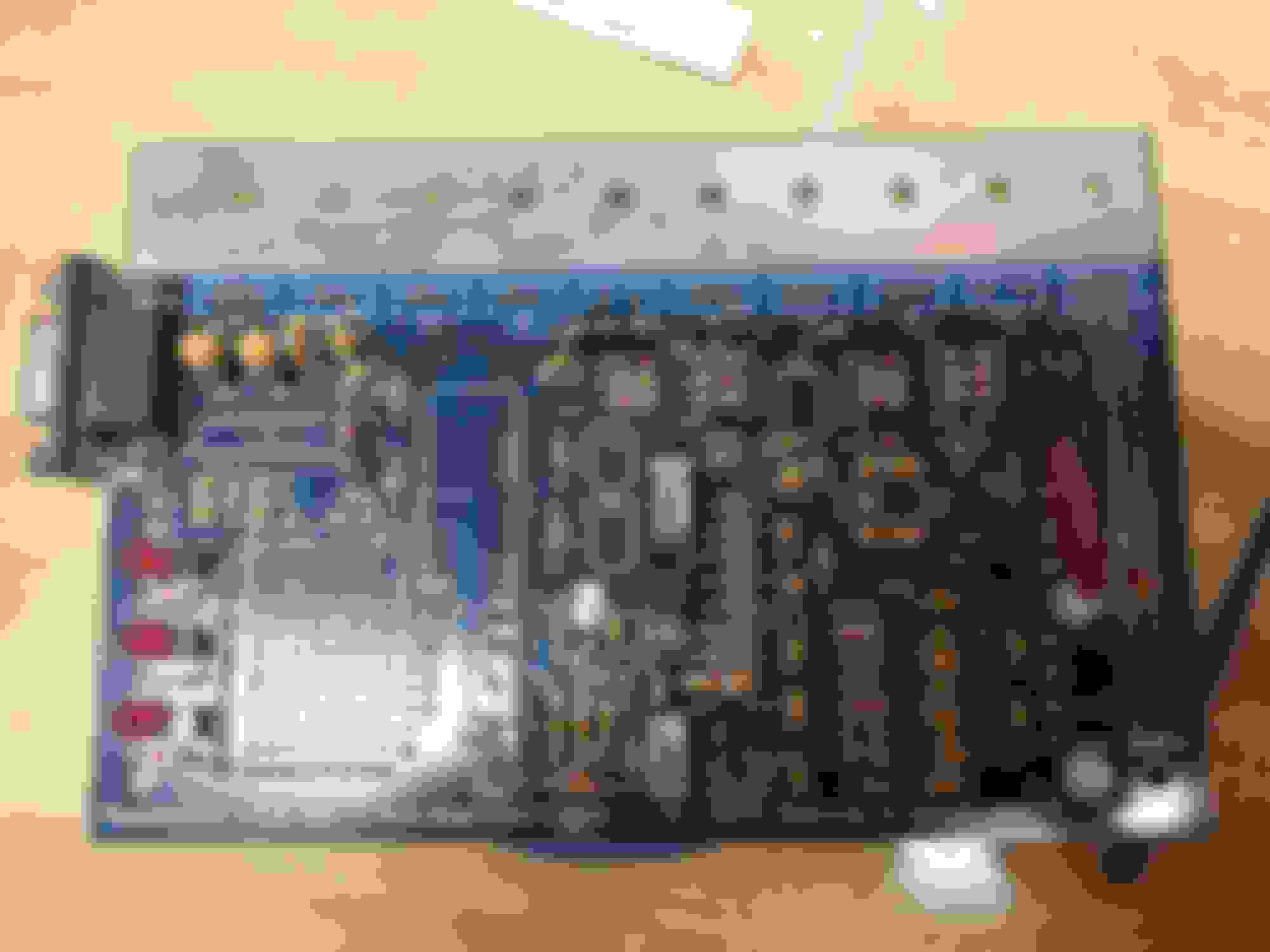
I just ask because I saw this picture from Oochi's MS3X build:
It looks like both DB37 connectors are used, in which case I should add that to component map you posted, correct?
Alright thank you Braineack. I ordered the expander board, the two 24" harnesses for the MS3 and MS3X, as well as the open element GM AIT kit with aluminum bung.
I also changed my mind about the UEGO and went with an MTX-L since it can do serial with the expander board, but I will cross that bridge when I get there.
I will take pictures of the at different levels of completion. PM me if you want any for the guide you will be making.
Is this "expander board" you're talking about the MS3x board, or a JBperf expander board? MS3x does not have serial wideband input.
No I bought the MS3X board. I was wrong about being able to run serial to the MS3X directly. According to this thread https://www.miataturbo.net/megasquir...-serial-69739/
you need to use the JBperf board you described in order to convert it to CAN, which the MS3X can read. Anyway, yeah, that's why I was going to do that later once I get this thing at least running.

 12-11-2016 | 03:41 PM


 0
0