
New Wing to Test
 12-10-2012, 10:28 AM
#101
Elite Member
iTrader: (15)

Join Date: Dec 2007
Location: San Antonio, Texas
Posts: 4,847
Total Cats: 27
I have tried four or five versions of wing mounts and have the holes in my trunk lid and transom to prove it.
I think this approach that Keith is working on will work fine (in fact rlogan and I have considered it before but had not tried it yet). That area of the body work where the mounts will attach is very stiff so it will transfer load well and be stable.
I am not really that worried about how far the trunk opens either. Since this is going on a track car the trunk lid will be gutted and all the stock hardware will be removed anyway.

Reply
 0
0

0
12-10-2012, 02:19 PM
#102


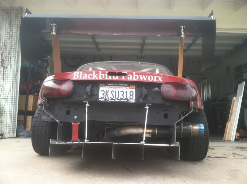
I've never been thrilled bout putting 100 lbs or so into the trunk lid. But more importantly in my case, I had hood pins right where the mounts would have gone - this made me look past the obvious mount. As ZX posted, the sides of the trunk opening are really strong and lend themselves well to taking the forces from the wing.
The only body mods are some holes in the side of the trunk opening for the mounting bolts. The lid shouldn't need any trimming - mine didn't. When the wing is off, nothing is visible. When I think about it, it's actually a good option for a dual-purpose car. We'll see how the prototype looks on a real car, not my poor little guy.
The only body mods are some holes in the side of the trunk opening for the mounting bolts. The lid shouldn't need any trimming - mine didn't. When the wing is off, nothing is visible. When I think about it, it's actually a good option for a dual-purpose car. We'll see how the prototype looks on a real car, not my poor little guy.
Reply
0
0
12-11-2012, 12:32 AM
#103
Supporting Vendor

iTrader: (3)

Join Date: Jul 2006
Location: San Diego
Posts: 3,303
Total Cats: 1,216
I weighed the pros and cons of the type of mount you're describing. It's just more weight IMO. If you've held 3/16" or 1/4" aluminum in your hands you'll see quickly how more of it can really add up the weight - and I'm trying to be severely weight-conscious. Running the uprights all the way down to the license plate or rear bumper area has more than one downside, not the least of which is that it's going to be nearly double the weight. Upsides are it gets the airfoil back more, and gives it more leverage on the back of the car. But, I was standing in the metal supply store, holding the material in my hands, and realized the weight of the upright could add up really fast - so I chose to try to come up with a design that goes to the trunk but still places the wing pretty far back.
Final fit will be in the next couple days so we'll see how that worked out.
Keith - your Targa V8 miata is hardly a "poor little guy" haha! I love that car.
-Ryan

Last edited by ThePass; 12-12-2012 at 11:59 AM.
Reply
0
0
12-12-2012, 12:02 PM
#104
Supporting Vendor
iTrader: (3)
Join Date: Jul 2006
Location: San Diego
Posts: 3,303
Total Cats: 1,216
Edited my previous post. I had said that I'm not a fan of Crusher's uprights, but that's not really the case - I actually am a fan of that style, but I made the call to save weight with a shorter upright when it came down to it for mine.
Reply
0
0

 12-22-2012, 05:31 AM
#110
Supporting Vendor
iTrader: (3)
Join Date: Jul 2006
Location: San Diego
Posts: 3,303
Total Cats: 1,216
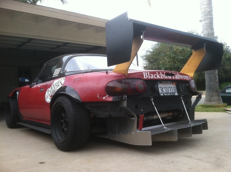
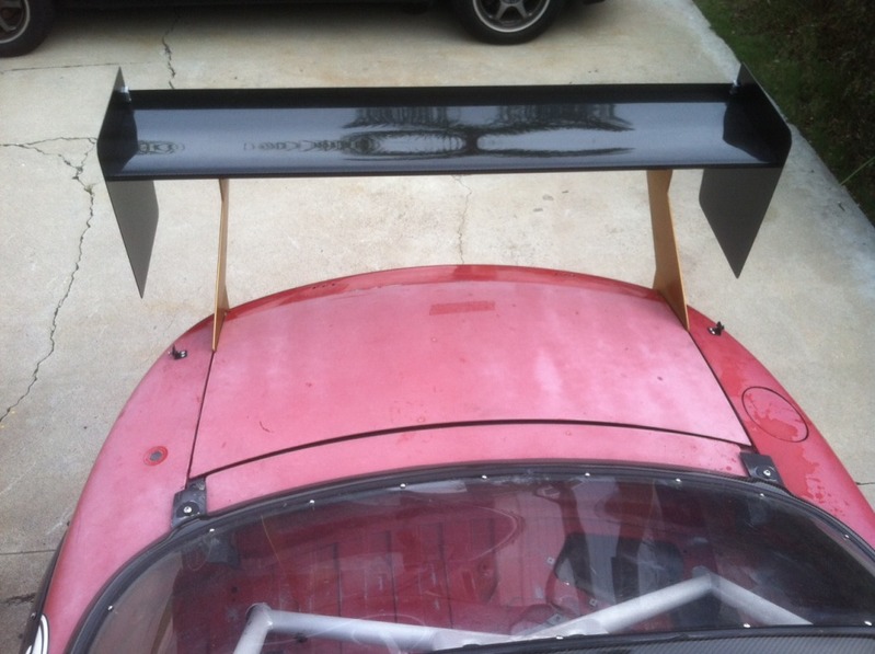
Fabrication is done, wing is mounted 
I fabricated both the uprights and the endplates. Had a shop do the bends, and then sent the uprights out for anodizing. Used the ARP hardware that came on the wing, as well as the aircraft grade heim joints for adjusting the angle of attack. I also cut down the steel mounts on the wing and drilled new holes in them to mount to the uprights.
Angle range of adjustment is -0.5* to +7.5* right now. Priority in design was moving the airfoil as far back as possible. Secondary focuses were keeping drag low, optimizing endplate dimensions and design, and keeping weight down.
Reply
0
0

 12-22-2012, 08:26 AM
#112

That's real sick. Bend angles look very small - your mounts must be a different width than keiths? My wing came yesterday and it has two sets of holes on the bottom for changing the width of the mounts.
Need more info on your endplates.
EDIT: No one worries about side-loading? Wind is about 30mph here today which would be .032 PSI (if I did that right). Sooo, 10 lbs is easily conceivable. Which seems low, but that's a pretty big moment arm... That's just for the end plate, not the upright.
Need more info on your endplates.
EDIT: No one worries about side-loading? Wind is about 30mph here today which would be .032 PSI (if I did that right). Sooo, 10 lbs is easily conceivable. Which seems low, but that's a pretty big moment arm... That's just for the end plate, not the upright.
Last edited by ericwh; 12-22-2012 at 09:10 AM.
Reply
0
0
12-22-2012, 09:53 AM
#114
The wings only have one mounting position in them, one hole at the front and one at the rear. The range of holes for adjusting has to be in the mounts. These wings should all be the same, they were a spec item. The only variation is the bolt-on end plates and the material for the show car wings.
I like the multi-hole setup because it's less drag (no turnbuckle messing up the airflow in the middle of the most important part of the wing) and easily repeatable. It only adjusts in steps, but there's about 1/4 degree between the different holes if my rough measurements are right. Doesn't look as cool though.
Side loads aren't really that much of a problem - someone else asked about them, so I tried pushing on mine. It had moved about 10mm until my feet started slipping on the garage floor, well over 10 lbs of side load. Not a major concern.
Reply
0
0
 12-22-2012, 06:19 PM
#117
Supporting Vendor
iTrader: (3)
Join Date: Jul 2006
Location: San Diego
Posts: 3,303
Total Cats: 1,216
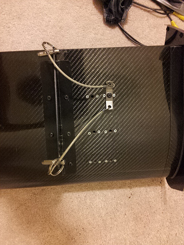
I wanted to relocate the holes - I didn't like that the rear hole is mere millimeters away from the carbon airfoil, and I wanted to have the adjustment of the angle done from the rear hole, not the front hole.
Also, the mounts are steel, so I wanted to slim those down and make up for the removed height with the aluminum upright to save a little weight.
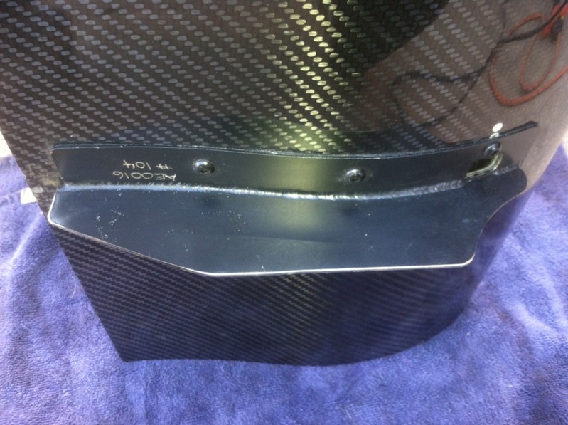
Two pics; first is of the mount as it came, with a sharpie line where I wanted to approximately cut it, second is after the cut:
Reply
0
0
12-22-2012, 06:21 PM
#118
Supporting Vendor
iTrader: (3)
Join Date: Jul 2006
Location: San Diego
Posts: 3,303
Total Cats: 1,216
That's real sick. Bend angles look very small - your mounts must be a different width than keiths? My wing came yesterday and it has two sets of holes on the bottom for changing the width of the mounts.
Need more info on your endplates.
EDIT: No one worries about side-loading? Wind is about 30mph here today which would be .032 PSI (if I did that right). Sooo, 10 lbs is easily conceivable. Which seems low, but that's a pretty big moment arm... That's just for the end plate, not the upright.
Need more info on your endplates.
EDIT: No one worries about side-loading? Wind is about 30mph here today which would be .032 PSI (if I did that right). Sooo, 10 lbs is easily conceivable. Which seems low, but that's a pretty big moment arm... That's just for the end plate, not the upright.
I don't think side-wind will be a problem at all, it is really sturdy. Flimsier uprights that have been swiss-cheesed with holes in them to make them lighter and that mount to the trunk surface may have issues in this area, I don't know.
-Ryan
Reply
0
0
12-22-2012, 11:14 PM
#119

I cut some height off of the mounts on the wing.
I wanted to relocate the holes - I didn't like that the rear hole is mere millimeters away from the carbon airfoil, and I wanted to have the adjustment of the angle done from the rear hole, not the front hole.
Also, the mounts are steel, so I wanted to slim those down and make up for the removed height with the aluminum upright to save a little weight.
Two pics; first is of the mount as it came, with a sharpie line where I wanted to approximately cut it, second is after the
Reply
0
0
12-23-2012, 03:37 AM
#120
Supporting Vendor
iTrader: (3)
Join Date: Jul 2006
Location: San Diego
Posts: 3,303
Total Cats: 1,216
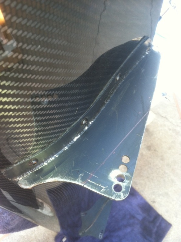
Hmm I see what you are saying. But, don't know how you figure there is more frontal area. Same number of bolts, same thicknesses of materials, in fact using the same exact hardware too. If you mean the frontal area shifted because the bolt locations moved, that I agree on.
As for the rear hole, as great as it is in theory, the carbon was already F'ed up from mounting/dismounting in its previous life because that hole is so close to the airfoil. I knew if I used that hole, through just tool contact, mounting/dismounting, etc. it would get a lot worse. I'd like to avoid causing a weak point in the airfoil over time.
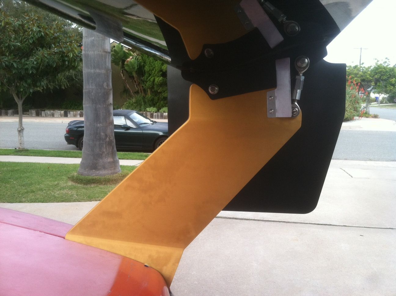
The other thing I took into consideration was that the front holes stuck wayyy down low - this meant the angle of the uprights would have to be more severe because they would have less height in which to make the transition. I wanted to minimize the angles of the bends to keep the aluminum as strong as possible. As it is, they are only 7* and 9*.
Relocating the mounting holes was a trade-off choice, but I ultimately didn't like how the upright had to be designed given the existing mounting setup.
Overall, I think it's not too bad on the frontal area/drag compared with a lot of upright designs I've seen on the market:
As for the rear hole, as great as it is in theory, the carbon was already F'ed up from mounting/dismounting in its previous life because that hole is so close to the airfoil. I knew if I used that hole, through just tool contact, mounting/dismounting, etc. it would get a lot worse. I'd like to avoid causing a weak point in the airfoil over time.
The other thing I took into consideration was that the front holes stuck wayyy down low - this meant the angle of the uprights would have to be more severe because they would have less height in which to make the transition. I wanted to minimize the angles of the bends to keep the aluminum as strong as possible. As it is, they are only 7* and 9*.
Relocating the mounting holes was a trade-off choice, but I ultimately didn't like how the upright had to be designed given the existing mounting setup.
Overall, I think it's not too bad on the frontal area/drag compared with a lot of upright designs I've seen on the market:
Reply
0
0


