

nerf bar design
 05-06-2013, 12:50 PM
#1
Junior Member
Thread Starter

Join Date: Apr 2011
Location: Oregon
Posts: 301
Total Cats: 4

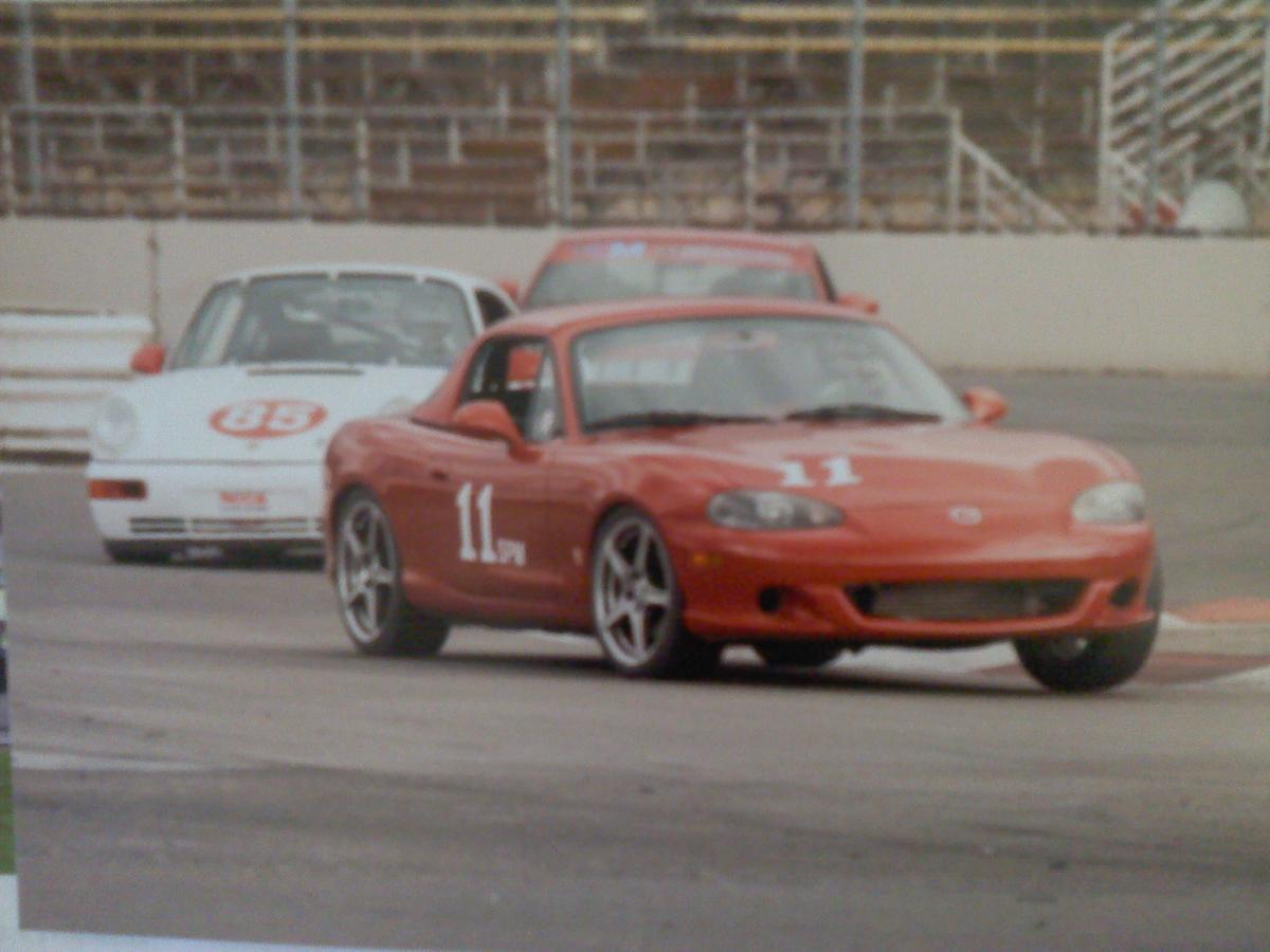
 Repairing front end damage done at the track last month.
I've got new sheet metal on the car now. I would like to replace the front OEM bumper substructure with something more formidable... and would like some design suggestions.
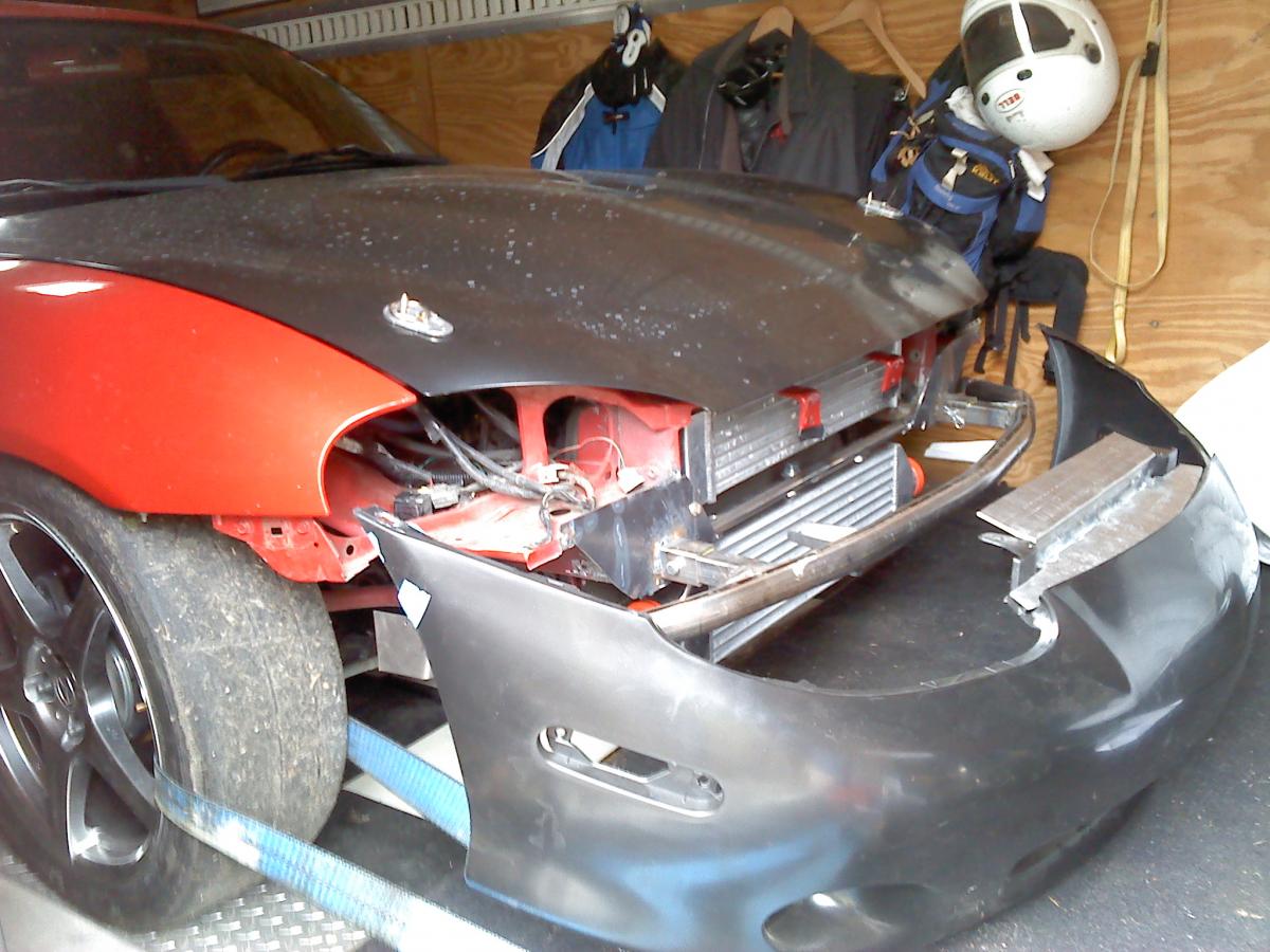
I had gotten some advice from Emilio. I believe he explained that he uses two small aluminum tubular "v's" that he bolts up under each side of the bumper cover. I was going to go with this design, but found that my core support was too damaged to repair. My design will have to replace the function of this core support; hang the intercooler and tie together the frame rails.
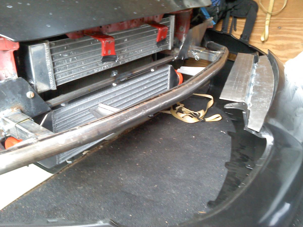
So far, I have cut the core support out and cut back the frame rails one inch, then welded a plate to box in the end of each frame rail. I think I will use this to mount a single continuous nerf bar; which will also tie together the frame rails.
One consideration is that I'd like the nerf bar to be sturdy enough to bump, but weak enough to deform (I want it to fail before the frame rails do). I am thinking that 1 1/2 .090 mild steel tubing; or perhaps .090 or even .060 high carbon steel.
Does anyone here have fabrication experience that might chime in?
Last edited by gtred; 05-06-2013 at 02:30 PM. Reason: added pics

Reply
 0
0

0
05-07-2013, 09:52 AM
#2
Junior Member
Thread Starter
Join Date: Apr 2011
Location: Oregon
Posts: 301
Total Cats: 4
Finalizing a design... thinking out loud. Any mechanical engineers out there; feel free to chime in.
I'll make the crash bar attached to the bumper cover. I'll use attachment stubs which will insert into receivers; a tube into tube. The receivers will be welded into the frame OEM frame rail and the nose attachment stubs will be pinned in place. The nose could then be easily removed so it wouldn't drag when loading into the trailer.
I am guessing that the light duty metal in the OEM frame rail might withstand 500# each before crumpling. I will use shear pins with that approximate rating. I will cap the stub and receiver and insert a bumpstop in-between the stub and receiver. I found one from a Ram Truck that deforms at 660# the first inch then 1000+# the second inch. This will lengthen instantaneous load and might mitigate some of the force to the frame rail.
I think that a 4' long 1 1/2" x .095 wall mild steel tubing for the crash bar would be reasonably matched to a distributed load 500# + 500#. Goal of keeping it under 15#; which is the weight of the structure that I've cut out so far.
Reply
0
0
05-23-2013, 08:16 PM
#3
Junior Member
Thread Starter
Join Date: Apr 2011
Location: Oregon
Posts: 301
Total Cats: 4
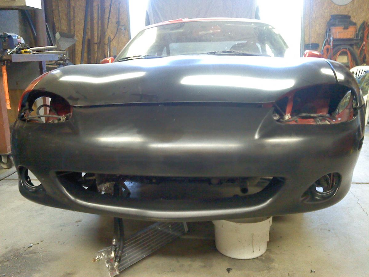
bumper isolators and nerf bar installed. frame tubes are reinforced. upper pin and lower dzeus attachment points for nose skin are now fitted. the whole nose can now be detached by pulling a couple of pins. ready for paint! at 7# 12 oz the nerf bar came in lighter than I had expected

Reply
1
1

 05-24-2013, 12:34 PM
#7
Junior Member
Thread Starter
Join Date: Apr 2011
Location: Oregon
Posts: 301
Total Cats: 4
...first lap... you know, red-mist + cold tires... a car tried to late brake and go 3 wide on the outside in the turn 5-6 transition, got into the marbles and spun across our noses.
Still having fun, but it's costing me points for missing now two races (ORP race is this weekend and I'm not ready)... and I'm poor again; no more fancy hotels and late night partying on race weekends. guess I'll be sleeping at the track again this season...
Mcfandango: I also have concerns about those frame rails. They are just thin steel boxes. I ended up using clevis pins for the telescoping tube connection. when I tested the connection with my sledge hammer, the pin did break with a hard whack and the two tubes connection did telescope.
I'm all for saving the frame rails, but I didn't quite get your suggestion; would you elaborate? Thx cj
Reply
0
0

Thread
Thread Starter
Forum
Replies
Last Post
Zaphod
MEGAsquirt
47
10-26-2018 11:00 PM
stoves
Suspension, Brakes, Drivetrain
5
04-21-2016 03:00 PM


