
Still can't get MS and LC-1 DB gauge readings to match
 05-15-2010, 09:51 PM
#1
Newb
Thread Starter

Join Date: Mar 2008
Posts: 20
Total Cats: 0
I made sure when I installed the LC-1 to solder every connection.
When I programmed the LC-1 unit I followed this exactly...
After I was done with the LC-1, I configured the MSPNP wideband setting to this...
INNOVATE_0_5_LINEAR -- Innovate, PLX 0-5 10-20:1 AFR
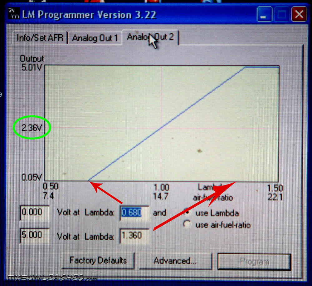
Then...changed the switch point to 2.36 and changed the setting to (wideband)
and after all that, the MS readout and the in-car DB gauge readout won't match. How do you get them to pair up? Im guessing I might have missed a step, but i doubt it...I double checked too many times
When I programmed the LC-1 unit I followed this exactly...
After I was done with the LC-1, I configured the MSPNP wideband setting to this...
INNOVATE_0_5_LINEAR -- Innovate, PLX 0-5 10-20:1 AFR
Then...changed the switch point to 2.36 and changed the setting to (wideband)
and after all that, the MS readout and the in-car DB gauge readout won't match. How do you get them to pair up? Im guessing I might have missed a step, but i doubt it...I double checked too many times

Reply
 0
0

0
05-15-2010, 10:02 PM
#2
Supporting Vendor


iTrader: (33)
Join Date: Jul 2006
Location: atlanta-ish
Posts: 12,659
Total Cats: 134
I assume you have output 1 going to your gauge and output 2 going to your ECU? How is output 1 configured?
How far off are the readings?
Where is the LC1 grounded?
EGO is set to wideband? (basic > exh gas settings > sensor type)
How far off are the readings?
Where is the LC1 grounded?
EGO is set to wideband? (basic > exh gas settings > sensor type)
Reply
0
0
05-15-2010, 11:39 PM
#3
Newb
Thread Starter
Join Date: Mar 2008
Posts: 20
Total Cats: 0
From the LC-1 unit
I ran the yellow wire (Analog output #1) to the MS ECU
and brown wire (Analaog output #2) to the gauge white wire
EGO is switched to wideband
here are the readings at these temp conditions...
coolant temp: 171 F
MAT: 108 F
DB gauge reading : 13.4-12.9 (bounces between these values)
MS WBO2 reading : 10.82-10.78 (same as above)
I have the LC-1, gauge, and calibration switch grounds soldered into a singular bigger grounds w/ a hole at the end and it shares the same nut as the ECU ground on the back of the motor.
Today someone mentioned to me that I solder the LC-1 ground into the ECU ground, will that give me a better reading matchup?
Last edited by malachi_fox; 05-16-2010 at 12:19 PM.
Reply
0
0
05-17-2010, 12:50 PM
#4
Supporting Vendor
Join Date: Sep 2006
Posts: 2,332
Total Cats: 67
You need to use that curve on Analog 1 instead, and use the curve shown in this link for Analog 2.
http://www.innovatemotorsports.com/s.../DB_manual.pdf
http://www.innovatemotorsports.com/s.../DB_manual.pdf
Reply
0
0
05-18-2010, 12:29 AM
#5
Newb
Thread Starter
Join Date: Mar 2008
Posts: 20
Total Cats: 0
update...
Analog 1 is scaled from 10-20:1 (ms ecu)
Analog 2 is scaled from 7.35-22.39 (db gauge)
I had the big gauge wire ground (LC-1, gauge, and calibration switch grounds) that runs to the end of the engine, now soldered into the two ECU wires.
So now, instead of two rear engine key hole wires held by the bolt, I have one key hole.
Even now, the MS WB reading isn't the same as the DB gauge, oh yeah i even calibrated it.
The DB gauge lights up differently on start up, the single left digit gives a quick flash but it still works, maybe due to a direct ECU ground connection
I'm assuming that this reading mismatch can only be cured by ECU adjustments, I just don't know what needs adjusting and even so...by how much?
Reply
0
0
05-18-2010, 04:23 PM
#7
Newb
Thread Starter
Join Date: Mar 2008
Posts: 20
Total Cats: 0
the readings now are MUCH closer
for instance the DB gauge will read 11.1
while the MS gauge will read 10.88
maybe i'm a perfectionist but are the two readings supposed to be exact right down to decimal?
what are acceptable discrepancies between the two?
for instance the DB gauge will read 11.1
while the MS gauge will read 10.88
maybe i'm a perfectionist but are the two readings supposed to be exact right down to decimal?
what are acceptable discrepancies between the two?
Reply
0
0
05-19-2010, 11:16 PM
#8
Elite Member
iTrader: (4)
Join Date: Aug 2009
Location: Redwood City, CA
Posts: 1,784
Total Cats: 42
How'd you fix it? My outputs are setup like yours and when the LC1 is warming up it'll give TS a somewhat beleivable number (around 14), and as soon as the gauge gets a reading, TS will show 9.00 and won't really move around much.
Reply
0
0
05-20-2010, 12:34 AM
#9
Newb
Thread Starter
Join Date: Mar 2008
Posts: 20
Total Cats: 0
heheheh^^^
I thought I fixed it until I did some data logging and found out how "off" the MS WB reading is
My datalog is attached btw...
If you open in MLV, you can definitely see the max and min MS WBO2 values.
They just absolutely STAY within 10-11 AFR when my gauge gets readings from 10 to 22 AFR. The weird thing is...when my gauge gets a leaner reading, the MS will show it getting richer
for instance, gauge will crawl up to 14 to 15 and the MS will show it creep down from 11 to 10. At this point being new to the whole MS tuning experience, I don't know which reading to trust.
The LC-1 is programmed as followed:
Analog 1 is scaled from 10-20:1 (ms ecu)
Analog 2 is scaled from 7.35-22.39 (db gauge)
The MS is also adjusted for the WBO2 when I installed it
My exhaust gas settings are also attached
I don't understand why MS can only read values between 10 and 11 when the gauge readings are much more broader.
There has gotta be a few people around here whom has had the same issues with MS LC-1 readings
Reply
0
0
05-20-2010, 12:55 AM
#10
Elite Member
iTrader: (4)
Join Date: Aug 2009
Location: Redwood City, CA
Posts: 1,784
Total Cats: 42
That sounds like what was happening to me...I just said **** it and started a new project and made damn sure that the WB setting was for LC1 0-5v and .5-1.5. Then, made damn sure the LC1 was outputting the same thing.
Problem is fixed. Though the gauge and MS are reading off by almost 1, at least its better than having it stuck at 9. Might wanna triple check everything...
Problem is fixed. Though the gauge and MS are reading off by almost 1, at least its better than having it stuck at 9. Might wanna triple check everything...
Reply
0
0
05-20-2010, 08:20 AM
#11
Junior Member

Join Date: Dec 2008
Location: Ft. Lauderdale, FL
Posts: 315
Total Cats: 9
One possible thing to do would be to hook the gauge up per the directions, i.e. hook the gauge up to output 1 and the Megasquirt to output 2. I would then reset the LC-1 to factory defaults. Go back in and assign output 2 to be AFR, not lambda, 0V=10AFR, 5V=20AFR. Then set the megasquirt to the same. Theoretically you should be able to use output 1 and output 2 anyway you want, but I have found the Innovate products to be really finicky.
You could also try setting the LC-1 back to defaults and copy the output 1 settings for the gauge into output 2, then change output 1 to AFR, 0-5 10:1-20:1. Then make sure that you have the megasquirt set to the same. I was having the same issue at first with my LC-1, where I could not get the correct values in megasquirt. I have since changed to a used LM-1 and integrated the hand held display portion into a radio block off plate. I have the same readings on the display as I am getting in Megasquirt and the readings were within .5 with the readings I was getting from the dyno. Good luck.
You could also try setting the LC-1 back to defaults and copy the output 1 settings for the gauge into output 2, then change output 1 to AFR, 0-5 10:1-20:1. Then make sure that you have the megasquirt set to the same. I was having the same issue at first with my LC-1, where I could not get the correct values in megasquirt. I have since changed to a used LM-1 and integrated the hand held display portion into a radio block off plate. I have the same readings on the display as I am getting in Megasquirt and the readings were within .5 with the readings I was getting from the dyno. Good luck.
Reply
0
0
05-20-2010, 08:35 AM
#12
Boost Czar

iTrader: (62)
Join Date: May 2005
Location: Chantilly, VA
Posts: 79,729
Total Cats: 4,126
After reading this thread, I decided to go out and run logworks and TS at the same time. I made half my laptop the logworks AFR gauge, and the other half a single AFR gauge in TS.
Values were so close it was too hard to find a discrepancy. However, Logworks updates from the sensor hellafaster than TS.
That is all, sorry I'm no help.
Values were so close it was too hard to find a discrepancy. However, Logworks updates from the sensor hellafaster than TS.
That is all, sorry I'm no help.
Reply
0
0
05-20-2010, 09:01 AM
#13
Elite Member
iTrader: (4)
Join Date: Aug 2009
Location: Redwood City, CA
Posts: 1,784
Total Cats: 42
I would then reset the LC-1 to factory defaults. Go back in and assign output 2 to be AFR, not lambda, 0V=10AFR, 5V=20AFR. Then set the megasquirt to the same. Theoretically you should be able to use output 1 and output 2 anyway you want, but I have found the Innovate products to be really finicky.
Reply
0
0
05-20-2010, 03:56 PM
#14
Newb
Thread Starter
Join Date: Mar 2008
Posts: 20
Total Cats: 0
Attached below is how I wired the LC-1. LC-1 and MS ground are one in the same(ie...they don't stack on one another, they are soldered into one).
Reason why me and many others bought and spent too much money on the LC-1 was because of its many features. Especially, that the analog outputs can be programmed. Now...if the LC-1 outputs can't be programmed to your specs, then why bother owning one?
Regarding the LC-1 install and MSPNP:
The yellow wire (analog output #2), I ran and soldered into the DIY provided wiring harness connector into pin #10, then connected to the ECU. I did this to ease removal and transferability (if that's a word) in case I total my car and want to transfer parts to another shell(been doin this for years lol).
Other than that I can't think of any other info I may be leaving out. If the LC-1 analog outputs can be programmed like innovate motorsports promises, the lc-1 outputs (either yellow or brown) can be wired either way and STILL should work.
The main issue is that the MS reads from 10 to 11. In addition it gets leaner when it ought to be richer. I can't and don't think switching outputs is gonna solve my problem as I already soldered everything to get legit connections. I've looked at my friends turbo miata LC-1 gauge readouts yesterday and we are similar.
I think the MS is only receiving a signal that consist of only 10-11
or I just didn't finish my scaling or configuration.
anyone live in norcal btw? it would be cool if someone could take a quick peek at detect anything fishy.
Reply
0
0
05-20-2010, 04:36 PM
#16
Junior Member
Join Date: Dec 2008
Location: Ft. Lauderdale, FL
Posts: 315
Total Cats: 9
Attached below is how I wired the LC-1. LC-1 and MS ground are one in the same(ie...they don't stack on one another, they are soldered into one).
Reason why me and many others bought and spent too much money on the LC-1 was because of its many features. Especially, that the analog outputs can be programmed. Now...if the LC-1 outputs can't be programmed to your specs, then why bother owning one?
Regarding the LC-1 install and MSPNP:
The yellow wire (analog output #2), I ran and soldered into the DIY provided wiring harness connector into pin #10, then connected to the ECU. I did this to ease removal and transferability (if that's a word) in case I total my car and want to transfer parts to another shell(been doin this for years lol).
Other than that I can't think of any other info I may be leaving out. If the LC-1 analog outputs can be programmed like innovate motorsports promises, the lc-1 outputs (either yellow or brown) can be wired either way and STILL should work.
The main issue is that the MS reads from 10 to 11. In addition it gets leaner when it ought to be richer. I can't and don't think switching outputs is gonna solve my problem as I already soldered everything to get legit connections. I've looked at my friends turbo miata LC-1 gauge readouts yesterday and we are similar.
I think the MS is only receiving a signal that consist of only 10-11
or I just didn't finish my scaling or configuration.
anyone live in norcal btw? it would be cool if someone could take a quick peek at detect anything fishy.
Reason why me and many others bought and spent too much money on the LC-1 was because of its many features. Especially, that the analog outputs can be programmed. Now...if the LC-1 outputs can't be programmed to your specs, then why bother owning one?
Regarding the LC-1 install and MSPNP:
The yellow wire (analog output #2), I ran and soldered into the DIY provided wiring harness connector into pin #10, then connected to the ECU. I did this to ease removal and transferability (if that's a word) in case I total my car and want to transfer parts to another shell(been doin this for years lol).
Other than that I can't think of any other info I may be leaving out. If the LC-1 analog outputs can be programmed like innovate motorsports promises, the lc-1 outputs (either yellow or brown) can be wired either way and STILL should work.
The main issue is that the MS reads from 10 to 11. In addition it gets leaner when it ought to be richer. I can't and don't think switching outputs is gonna solve my problem as I already soldered everything to get legit connections. I've looked at my friends turbo miata LC-1 gauge readouts yesterday and we are similar.
I think the MS is only receiving a signal that consist of only 10-11
or I just didn't finish my scaling or configuration.
anyone live in norcal btw? it would be cool if someone could take a quick peek at detect anything fishy.
Reply
0
0
05-20-2010, 05:00 PM
#17
Newb
Thread Starter
Join Date: Mar 2008
Posts: 20
Total Cats: 0
Ben: correct, meant to say that 
MX5RACER: if push come to shove, I just might swap inputs. This thing causing me to doubt myself has me checking and re-checking my values in damn near every table regarding WBO2 configuring. I just can't see anything wrong, and everyone I've told tell me the same.
my biggest fear with doing so(output swap), is my problems will worsen (ie no reading whatsoever, heard too many no-read stories here). Or my problems will swap, like the gauge will read between 10-11 and MS will read 10-20. (can't leave out that possibility too now)
I'm just soooooo close to getting this thing dialed in. The only thing holding me back is the MS WBo2 reading.
The fact that MS receives WB reading period is a good thing. The issue is the reading only consists between 10-11, why is this happening, I don't know, but i'm trying to find out why....
Reply
0
0
05-21-2010, 03:17 PM
#19
Newb

Join Date: Apr 2010
Location: Charleston, SC
Posts: 4
Total Cats: 0
I just hooked my LC-1 up today to my DIY PNP and guage. I used the brown (output #2) for the guage and megasquirt because the manual says the guage is set up to read the output from the brown wire. Everything works well, I too soldered the connections and grounded at the ecm location.
Reply
0
0
05-22-2010, 10:43 AM
#20
Supporting Vendor
iTrader: (33)
Join Date: Jul 2006
Location: atlanta-ish
Posts: 12,659
Total Cats: 134
I just hooked my LC-1 up today to my DIY PNP and guage. I used the brown (output #2) for the guage and megasquirt because the manual says the guage is set up to read the output from the brown wire. Everything works well, I too soldered the connections and grounded at the ecm location.
Reply
0
0


