When you click on links to various merchants on this site and make a purchase, this can result in this site earning a commission. Affiliate programs and affiliations include, but are not limited to, the eBay Partner Network.
Possible Fab9 COP Tach fix when used on 92 1.6 with MSPNPv2
Connection to be made to use Fab9 COP to a 1992 miata with a MSPNP V2.
Coils 1&4
Coils 2&3
Power
Ground
Tach Input
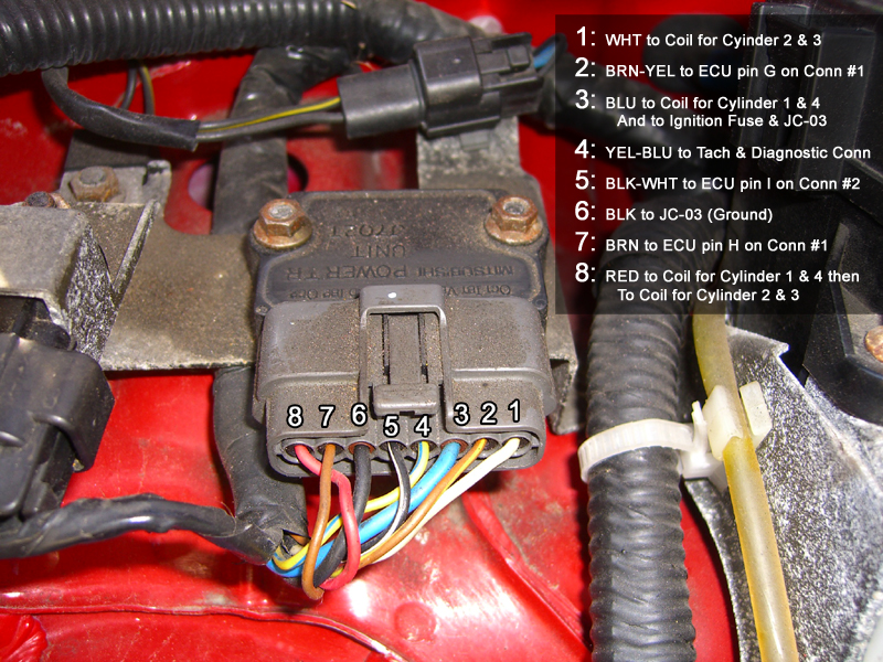
Wires used from the 92 Ignitor
Wires 2, 3, 6 & 7
2 — Brown with yellow stripe - Coils 1&4
3 — Blue - Power
6 — Black - Ground
7 — Brown - Coils 2&3
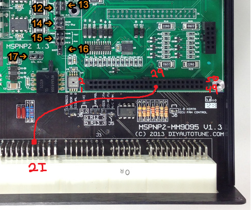
Connect the Yellow wire with the blue stripe in the diagnostics box to pin 11 on the expansion harness connected to the MSPNP V2.
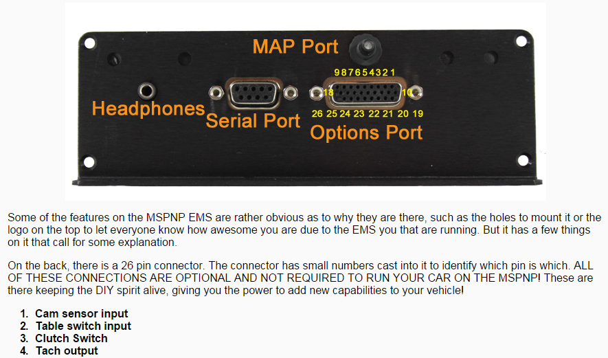
In Tunerstudio Under expansion Extended - Tacho output
Set Tacho output enabled to “On”
Set Output on to “D14”
Leave Speed set to normal.
Burn your changes, and close the window.
Save your MSQ, and exit Tunerstudio. Turn the car completely off, and the back on. You should now have a tach at the gauge cluster.
Additional - I used a molex connectors to make a weather resistant yet removable connection for flashing firmware without have to disconnect the individual coils.
Thanks to both Bryan from Fab9 for his feedback, and Matt at DIY for helping me find a solution.
I can't guarantee this info will help anyone running a different setup, but I found a few others with setups similar to mine asking the same questions with no resolution.
There's a wire at the ignitor that goes directly to the tach, and there's another on the ECU harness that goes to the ignitor. black/white and blue/yellow IIRC. If you splice those two together at the ignitor, you can use OEM wiring in the ECU harness to drive pin 11 or whatever. No need to run any extra, no need to do anything at the diag box.
I was unaware this was a big mystery, the stickies are super helpful.
Yep. I did, and it worked. I wondered about other options but I was isn't positive they would work. At one point I saw a response that said don't do anything on the harness side so i didn't. In the end it works and that was my goal.
The Fab9 cops have 4 wires. One for coils 1&4, one for coils 2&3, one wire for ground, and one for power. The original instructions said to connect the two tach signals from the ignitor harness together and connect them to power (12V). I asked Bryan about this before doing it, and he said I should leave them disconnected.
I ran everything as suggested, and start up was fine. I had a tach signal at the MS, but not at the cars dash. I contacted Bryan, he said he wasn't sure but thought I needed to connect something else to the MS and change a setting. I also contacted Diy to see if they had worked with the issue. Based on the feedback from both sources, and going through the forums I realized I could get a source signal from the diagnostic port. Just to be clear I tried the resistor fix first. So ..... based on what I was told, including that I should not be connection anything to the ecu harness I worked this solution. Now I freely admit I may have misunderstood something that I saw but again it did work. I'm more than happy to modify it for a better solution since I would prefer to not have an additional unneeded wire. But I've learned sometimes questions here don't get answered so I acted.
BTW I get it, this is no one's job so you're not obligated to respond or provide info.
You DO need to connect to the ECU harness to get a pseudo-crank driven tach signal without adding any extra wires, resistors, or any other crap.
There's three things you need to know blue/yellow, black/white, and 2I. Splice them all together and wire it to pin 11, that's it. Think about it hard for a second, look at a stock wiring diagram, you'll see that what you've done is identical without all the extra wire.
CAS driven tach > coil driven tach, IMO. Your coil wiring is already done and you have the means of making a tach pulse, not really easier.
 05-25-2015, 03:22 AM


 0
0