When you click on links to various merchants on this site and make a purchase, this can result in this site earning a commission. Affiliate programs and affiliations include, but are not limited to, the eBay Partner Network.
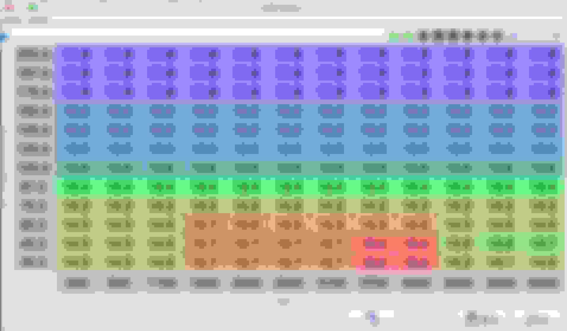
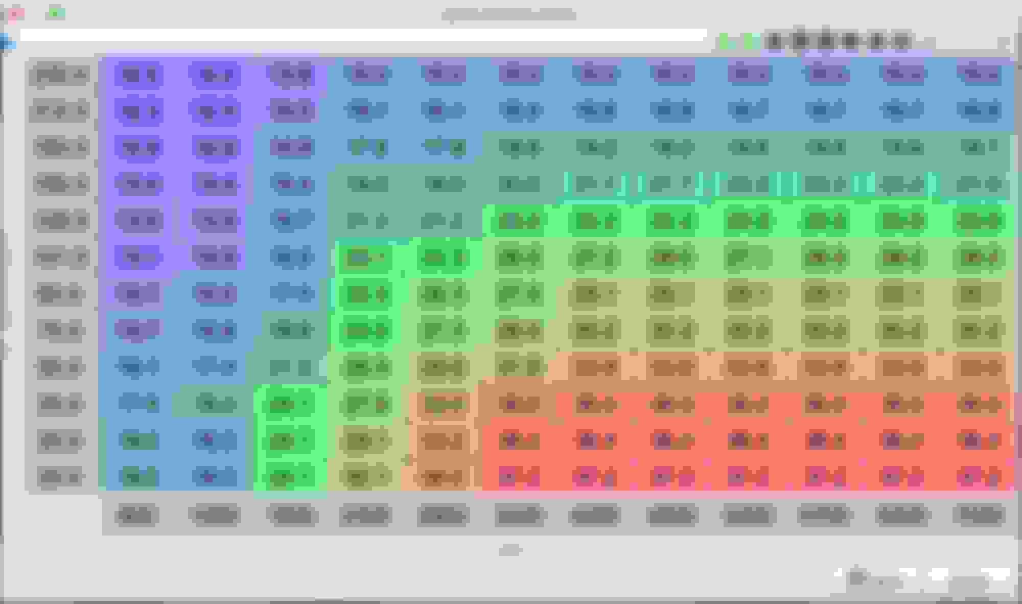
Getting ready to start road tuning. Could you all glance at my settings?
Got the car idling and the base timing set. Since this is just a startup map and I am VERY new at this, I figured it would be smart to see if some of you all would be willing to check my settings before I go running wild with the auto tune functionality. Vehicle and Parts: 2000 Miata, MS2 PNP, GM intake air temp sensor, AEM Uego Wideband, aftermarket exhaust. (everything else is stock, including injectors) Current problems: the wideband reads high in tuner studio. I set it up as a custom linear wideband and used the voltage settings in the AEM documentation.
Thanks in advance!
Your Idle AFR is weird, set the 14.0 cells to 14.7, should be easy with sequential injection. Same with your Idle timing, I would change the cells to 10-15 degrees, somewhere in that range for consistency. Is the MS2 unable to do sequential injection? From what I read untimed injection isn't the best, see if you can get sequential setup before starting tuning if possible. How is your wideband grounded? If one of the two grounds is off it could cause the inconsistency, I would fix that before doing any tuning. Mine is wired in without CANbus and the difference is within +/- .1 AFR at all times. AFR Targets and Timing looks fine other than that for a starting point.
Your Idle AFR is weird, set the 14.0 cells to 14.7, should be easy with sequential injection. Same with your Idle timing, I would change the cells to 10-15 degrees, somewhere in that range for consistency. Is the MS2 unable to do sequential injection? From what I read untimed injection isn't the best, see if you can get sequential setup before starting tuning if possible. How is your wideband grounded? If one of the two grounds is off it could cause the inconsistency, I would fix that before doing any tuning. Mine is wired in without CANbus and the difference is within +/- .1 AFR at all times. AFR Targets and Timing looks fine other than that for a starting point.
I will make the changes in my AFR and timing tables.
I believe the MS2 can do sequential injection. This is a topic I need to do some research on though. Untimed injection is just how this map came.
Two grounds on the Uego? This could be my issue. I am only aware of the one black wire that is in the harness that includes power, 5v signal and the data logging wire. Where is the other?
Thanks for the advice!
Last edited by atotalpro; 07-19-2019 at 01:45 PM.
Reason: Forgot to say thanks.
What model UEGO do you have? I have a 30-0300 X and it came with two grounds, its possible your model only has 1 ground. If you can't switch to sequential 14.0 is fine for the AFRs at idle.
EDIT - Found the model from your build thread. The 30-4110 only has one ground, which I believe should go to a chassis ground. My wideband has a ground wire I connected to the MS3, and another ground I connected to the engine block ground.
What model UEGO do you have? I have a 30-0300 X and it came with two grounds, its possible your model only has 1 ground. If you can't switch to sequential 14.0 is fine for the AFRs at idle.
I think its the 30-4110. Here is how my ground is set up, minus the extra ground I had piled on for my radar detector.
Not sure how I feel about that ground, I haven't really seen it used, at least in a photo for a wideband ground. I ran a wire to the ground wire on my engine block, not sure if the preferred ground location for a wideband with one ground wire would be to the megasquirt (if it has one integrated for accessories) or a chassis ground.
Disclaimer, I am electrically very poor. Take this with a grain of salt, very possible that ground is fine.
Just fix the discrepancy before even attempting to road tune, garbage in garbage out
Not sure how I feel about that ground, I haven't really seen it used, at least in a photo for a wideband ground. I ran a wire to the ground wire on my engine block, not sure if the preferred ground location for a wideband with one ground wire would be to the megasquirt (if it has one integrated for accessories) or a chassis ground.
Disclaimer, I am electrically very poor. Take this with a grain of salt, very possible that ground is fine.
I'll try a different ground location tonight. I think there is one available at the O2 sensor plug if I remember correctly. I assume that would go to the ecu or at least a good chassis ground.
Edit: So per this document from Flyin Miata that ground available at the O2 sensor harness is a "signal ground" would that be good to use?
That sounds good to me, I would recommend looking around this forum and see how other people ground single ground widebands and just mimic their setup. Trust but verify
Yeah that's not a proper ground location. That isn't your primary issue though.
If you do some searching you'll see some discussion about it, but basically you'll need to adjust the values in the custom wideband setup until the gauge matches what TS shows. The values AEM provides will not work.
Yeah that's not a proper ground location. That isn't your primary issue though.
If you do some searching you'll see some discussion about it, but basically you'll need to adjust the values in the custom wideband setup until the gauge matches what TS shows. The values AEM provides will not work.
In regards to the grounding location, are you referring to the one I am currently using?
I looked around and found a thread I had started reading, but didnt read all the way through. I guess I've never been a fan of doing my homework. Looks like I probably just need to lower the top afr value a bit. I'll give that a go tonight.
A proper ground will make your life easier in the long run, especially if you plan on using EGO and not redoing your calibration every week. I'd heed the advice in that thread (or the FM manual, whatever).
And no, the big iron shell with 20 different spinning, ferretic components in it does not count.
Alright, I see where you are coming from. Is it an issue though, that the signal ground and heater ground are one in the same for this wideband? Someone on another thread was saying that you dont want to put the heater ground on a signal ground, thus the Uego should be on some sort of chassis ground.
Yeah, I don't like that there isn't a metal bolt head on the ring terminal, however if your wideband powers on, your ground is fine. Change your settings in TS to match the gauge, or average the two. You wouldn't believe the number of cars I've tuned without freaking out about the wideband ground. I usually have three gauges, the dyno, TS, and the gauge. They're generally within half a point of each other, and freaking out about that is only going to waste your time. Generally you tune N/A cars in the 12.8-13.5 range at WOT, turbo cars 11.0-11.7 range, so stay in that window and go street tune. Other than that, as others have said lean out your idle to ~14.5, target 950 idle rpm, and throw in some idle advance swing to stabilize your idle.
Yeah, I don't like that there isn't a metal bolt head on the ring terminal, however if your wideband powers on, your ground is fine. Change your settings in TS to match the gauge, or average the two. You wouldn't believe the number of cars I've tuned without freaking out about the wideband ground. I usually have three gauges, the dyno, TS, and the gauge. They're generally within half a point of each other, and freaking out about that is only going to waste your time. Generally you tune N/A cars in the 12.8-13.5 range at WOT, turbo cars 11.0-11.7 range, so stay in that window and go street tune. Other than that, as others have said lean out your idle to ~14.5, target 950 idle rpm, and throw in some idle advance swing to stabilize your idle.
Curly, thanks for your response. I will try and find a better ground where I at lest have a nut or bolt contacting the ring terminal ( and then I will forget about it lol). Is there a particular method to calibrating TS to the gauge? I have just been using guess and check with the upper and lower values.
What do you mean by idle advance swing? I have that heard that term before.
One last question. Im having a little trouble understanding how to relate the AFR table to the VE table and both to throttle position or vacuum. What do the Y values of "AFR Load %" and "Fuel Load %" mean exactly and how do those both relate to each other and throttle position or vacuum? Im just having some trouble understanding what portions of the table get used when, particularly with the Y axis. I might be a little behind on the ICE theory.
Edit: I guess my main point of confusion is that I though the Y axis was supposed to be manifold pressure.
Thanks!
Last edited by atotalpro; 07-22-2019 at 09:52 AM.
Reason: more info
1) Unless you specifically changed it; Y axis on VE, AFR, and Advance is MAP. Under General Settings, if you have selected "Speed Density", then vertical axis is MAP.
2) Never use a thermoplastic material as part of a clamping mechanism for an electrical connection. When it creeps, the compression will be lost and resistance will increase.
 07-19-2019, 01:04 PM


 0
0


