
Where to mount nozzle?
 02-13-2010, 10:03 PM
#21
Junior Member
Thread Starter
iTrader: (1)

Join Date: May 2009
Location: Niagara Falls, ON
Posts: 431
Total Cats: 2
Ok, I guess I need to take a step back here.
There are two fundamental ways to do WI with the MS.
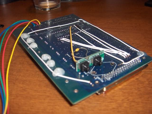
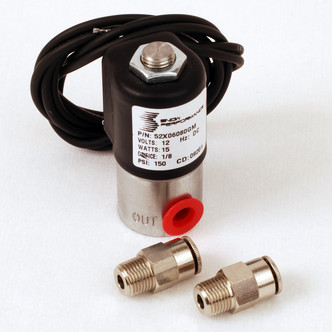
Way #1 involves using a high-speed solenoid (such as the one sold by AquaMist) which is pulsewidth modulated by the MS just like a fuel injector. When the MS wants to inject, it does two things- turn on the pump, and start driving the solenoid. Thus, you have two outputs of the MS to deal with, a relay driver to power the pump, and a PWM driver to power the solenoid. Here's the MS documentation on this mode: MSnS-Extra Hardware Manual
Way #2 is far cheaper, and sounds like what you're shooting for based on the list of hardware you've given. It consists of half of the circuit from the above example- the relay driver.
This is nothing more than a transistor wired to a pin of the CPU on one side, and a terminal of the DB37 connector on the other. Since the CPU itself is not capable of sinking enough power to drive a relay, we use the transistor to do that job. All you do is set that output to come on above a certain MAP, and that's it. There's no control over the quantity of water being injected, it's just on or off like the basic Snow circuit we've shown above.
Here's the documentation on general purpose relay driver outputs: MSnS-Extra Hardware Manual
There are two fundamental ways to do WI with the MS.
Way #1 involves using a high-speed solenoid (such as the one sold by AquaMist) which is pulsewidth modulated by the MS just like a fuel injector. When the MS wants to inject, it does two things- turn on the pump, and start driving the solenoid. Thus, you have two outputs of the MS to deal with, a relay driver to power the pump, and a PWM driver to power the solenoid. Here's the MS documentation on this mode: MSnS-Extra Hardware Manual
Way #2 is far cheaper, and sounds like what you're shooting for based on the list of hardware you've given. It consists of half of the circuit from the above example- the relay driver.
This is nothing more than a transistor wired to a pin of the CPU on one side, and a terminal of the DB37 connector on the other. Since the CPU itself is not capable of sinking enough power to drive a relay, we use the transistor to do that job. All you do is set that output to come on above a certain MAP, and that's it. There's no control over the quantity of water being injected, it's just on or off like the basic Snow circuit we've shown above.
Here's the documentation on general purpose relay driver outputs: MSnS-Extra Hardware Manual

Reply
 0
0

0
02-15-2010, 10:49 PM
#22

Mike
I found this:
Pin 25 – Output on JS0 (fan/water injection output) – External Connection – Light Blue Wire – This output grounds to activate fan or water injection system. Programmable in Megatune
here:
Megasquirt for Rick96Pgt
Not sure if that is what you're already working on.
Also. I was thinking that you might want to wire the Elect. Boost Controller relay in series with the float switch. This would provide safety by cutting boost if you ran out of fluid.
-Jo
Last edited by dynodragon; 02-15-2010 at 10:58 PM. Reason: add info
Reply
0
0
05-15-2010, 08:24 PM
#23

Mike
I found this:
Pin 25 � Output on JS0 (fan/water injection output) � External Connection � Light Blue Wire � This output grounds to activate fan or water injection system. Programmable in Megatune
here:
Megasquirt for Rick96Pgt
Not sure if that is what you're already working on.
Also. I was thinking that you might want to wire the Elect. Boost Controller relay in series with the float switch. This would provide safety by cutting boost if you ran out of fluid.
-Jo
Reply
0
0
05-16-2010, 11:11 AM
#24
Junior Member
Thread Starter
iTrader: (1)
Join Date: May 2009
Location: Niagara Falls, ON
Posts: 431
Total Cats: 2
Ahh i dont know about that you can email him and ask him, heres the website. http://www.dragonwerks.ca/
Or if someone knows here. Im going to see him in a month to get it retuned with the new setup so il see how it goes.
Or if someone knows here. Im going to see him in a month to get it retuned with the new setup so il see how it goes.
Reply
0
0

 07-27-2010, 10:46 PM
#27

I apologize for digging up an old thread, but have a fundamental question.
If the point of water injection is to cool the charge through evaporative cooling, then why put the IAT BEFORE the injector? It seems to me you would treat this like an intercooler, and have the IAT measuring the air charge temperature AFTER the injector (sufficiently after that most of the evaporative cooling has taken place).
I'm missing something. Appreciate the help. I'm planning to do this with my MSPNP.
Reply
0
0
07-28-2010, 10:15 AM
#28
Found a write-up on water injector placement here:
http://www.alcohol-injection.com/art...tion-nozzle-2/
Bottom line, Devil's Own recommends that most users place their water injector post-intercooler and as far upstream from the IAT sensor as possible to allow the IAT sensor to see the cooling effect. The exception would be more sophisticated WI users that are doing direct port injection -- which seems to raise a number of other issues.
A side benefit of this is an "automatic" safety feature that can be enabled by Megasquirt users. With Megasquirt, we can retard timing based upon high IAT. Thus, if WI were to fail for any reason, timing would retard to help spare the engine.
The initial post on this thread stated that WI should be post-IAT sensor, and I have seen this on other threads too. I've never seen a good explanation as to why. Anyone have a thought? Thanks, and I hope the link is useful.
Reply
0
0
08-12-2010, 07:30 AM
#29

Found a write-up on water injector placement here:
http://www.alcohol-injection.com/art...tion-nozzle-2/
Bottom line, Devil's Own recommends that most users place their water injector post-intercooler and as far upstream from the IAT sensor as possible to allow the IAT sensor to see the cooling effect. The exception would be more sophisticated WI users that are doing direct port injection -- which seems to raise a number of other issues.
A side benefit of this is an "automatic" safety feature that can be enabled by Megasquirt users. With Megasquirt, we can retard timing based upon high IAT. Thus, if WI were to fail for any reason, timing would retard to help spare the engine.
The initial post on this thread stated that WI should be post-IAT sensor, and I have seen this on other threads too. I've never seen a good explanation as to why. Anyone have a thought? Thanks, and I hope the link is useful.
http://www.alcohol-injection.com/art...tion-nozzle-2/
Bottom line, Devil's Own recommends that most users place their water injector post-intercooler and as far upstream from the IAT sensor as possible to allow the IAT sensor to see the cooling effect. The exception would be more sophisticated WI users that are doing direct port injection -- which seems to raise a number of other issues.
A side benefit of this is an "automatic" safety feature that can be enabled by Megasquirt users. With Megasquirt, we can retard timing based upon high IAT. Thus, if WI were to fail for any reason, timing would retard to help spare the engine.
The initial post on this thread stated that WI should be post-IAT sensor, and I have seen this on other threads too. I've never seen a good explanation as to why. Anyone have a thought? Thanks, and I hope the link is useful.
I'd be interested to know this too.
Reply
0
0
 08-23-2010, 10:05 PM
#31

we use W/MI a lot in the mazdaspeed world..pushing our stock turbos to their deaths.
in our case we have an intake air temp, as well as as boosted air temp which is in the intake manifold... we tap and put the nozzles in the cold pipe just before the TB, which goes along with the Devils own info. (i have always used DO meth kits as well).
starting from the intercooler to TB i plan to run in this order IC->(most of the piping)->bov flange->meth nozzle->IAT->TB. I would definitely try to place the nozzle after the bov flange too, espcially if you're running VTA so you're not throwing meth all over the engine bay haha.
Reply
0
0
05-12-2012, 04:34 PM
#32

Does it matter where I place the nozzle(s) in reference to the IAT sensor if I am using it to raise my safety margin? I'm not looking to increase timing as a result of lower IATs.
I have a 90* silicone bend before the TB, can I place the nozzle in the straight section of this or will the water condense on the bend? I wouldn't mind drilling and taping the intake manifold, but I am only using one nozzle, and don't want to starve a cylinder.
I have a 90* silicone bend before the TB, can I place the nozzle in the straight section of this or will the water condense on the bend? I wouldn't mind drilling and taping the intake manifold, but I am only using one nozzle, and don't want to starve a cylinder.
Reply
0
0
05-12-2012, 04:39 PM
#33
potential issue with doing it on the intake mani is siphoning the liquid at idle, since theres very high vacuum in there. using a solenoid over a check valve should make this not an issue though.
I put mine after the IAT, so it had no effect on it and thus fueling calcs... i figure this is more 'accurate'. One advantage to putting the nozzle before IAT I could see if it would probably be very obvious if the nozzle were to clog, pump take a ----, etc.
I put my IAT right after intercooler exit, and nozzle a few inches before TB.
Reply
0
0
05-12-2012, 04:46 PM
#34
Yeah, came across the siphoning issue upon more searching. My IAT sensor is also right after the IC, so not really looking to put the nozzle down there or relocate the IAT. I think I'll just do it in the standard location before the TB since it's a pretty trivial thing I am trying to accomplish. Thanks.
Reply
0
0
 05-22-2012, 01:19 PM
#37
Sounds about right. Another reason I'm getting away from WI... just it's general lack of precision. Anyways I don't think it's an issue at all, but 5-10 seconds does sound a little long. Is the check valve good to go? I can see it spraying a little long mess with AFRs/tune a little depending on the situation, but I wouldn't be too worried about it. Might be worth getting a good solenoid.
Reply
0
0
05-22-2012, 01:57 PM
#39
I never did any sort of tests to see if it stopped spraying immediately after the pump turned off, but it almost certainly was not in the order of 5-10 seconds...
http://www.alcohol-injection.com/en/...eck-valve.html
http://www.alcohol-injection.com/en/...eck-valve.html
Reply
0
0


