
Where to mount nozzle?
 02-04-2010, 03:35 PM
#1
Junior Member
Thread Starter
iTrader: (1)

Join Date: May 2009
Location: Niagara Falls, ON
Posts: 431
Total Cats: 2
Alright im about to buy a FM stage one water/meth kit. I Have the Begi S4 kit, so I was reading the nozzle has to be after the IAT sensor, and right now my bung for the IAT sensor is at the top right before the throttle plate. So do i mount the nozzle in the existing hole where the IAT was and drill a new hole down further the intercooler pipe and mount the IAT there? Thanks. Mike

Reply
 0
0

0
02-04-2010, 03:42 PM
#2
Supporting Vendor


iTrader: (33)
Join Date: Jul 2006
Location: atlanta-ish
Posts: 12,659
Total Cats: 134
Point the nozzle directly at the throttle plate. So it would be on the elbow of the BEGi cold side pipe right at the throttle body.
If the IAT sensor is in the way, my favorite place to put it is the cold side end tank of the intercooler. That should limit IAT heat soak that sometimes causes poor hot starting.
If the IAT sensor is in the way, my favorite place to put it is the cold side end tank of the intercooler. That should limit IAT heat soak that sometimes causes poor hot starting.

Reply
0
0
 02-05-2010, 02:57 PM
#7
Junior Member
Thread Starter
iTrader: (1)
Join Date: May 2009
Location: Niagara Falls, ON
Posts: 431
Total Cats: 2
Yea see the shitty thing is where it is now because we welded the bung in the intercooler pipe, and its almost to far down to put the nozzle directly at the throttle plate so i might have to order a new intercooler pipe or i might be able to just make it. Or il cut out the old bung weld the hole closed. Il think of something.
Reply
0
0
02-05-2010, 03:54 PM
#8
My setup was originally like that, except it wasn't even a bung, it was a hole Corky drilled and tapped into the intake elbow.
I got a pipe plug in the same size as the IAT hole, and drilled it out to accept the nozzle as well, as milling it down as flat as possible. I then took my unused IAT bung and welded it to the first coldside pipe, in front of the radiator, and put the sensor there.
No more heat soak, and good nozzle placement.
Reply
0
0
02-05-2010, 04:45 PM
#9
Elite Member
iTrader: (15)

Join Date: Dec 2007
Location: San Antonio, Texas
Posts: 4,847
Total Cats: 27
Yeah even though it is thin wall pipe (tubing) you might be able to get away with tapping a hole directly in the wall of the pipe. Just put some sealant on it. I did this myself with a BEGI intake tube (high pressure side) and it worked fine.
Reply
0
0
02-12-2010, 12:29 PM
#11
Junior Member
Thread Starter
iTrader: (1)
Join Date: May 2009
Location: Niagara Falls, ON
Posts: 431
Total Cats: 2
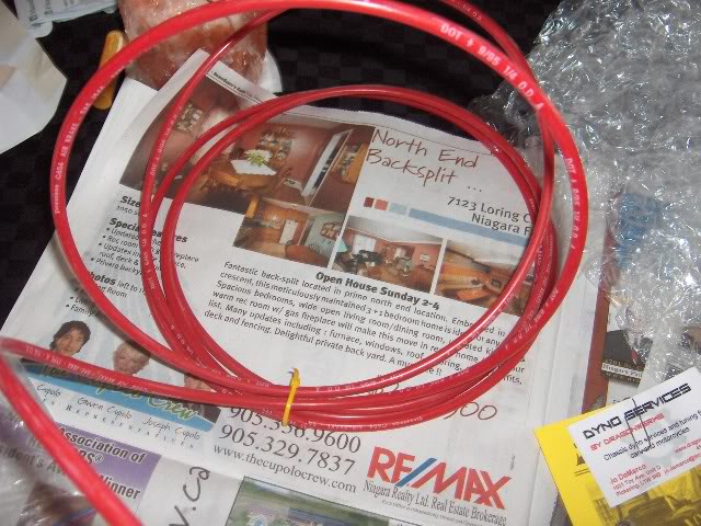
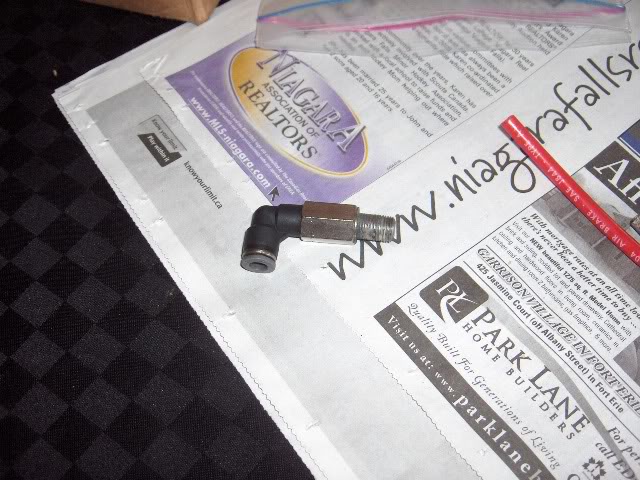
Well the kit came in today here are some pictures...
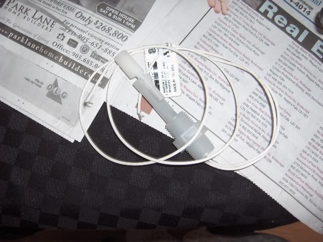
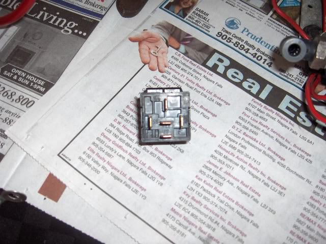
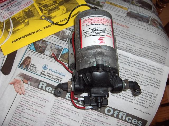
the only thing im stumped on is the relay. Kit came with no instructions so i went to the snow performance website, they show the colours for the wires for the relay but there are 5 terminals on the relay and i have no idea which wire goes to what terminal on the relay. So if anyone knows that would help me out. Now to find a bottle and where to mount it. I see people use there washer fluid but i would like to keep my washer fluid. Anyone have any picture of where they mounted there bottles and which one they used? Thanks, Mike
the only thing im stumped on is the relay. Kit came with no instructions so i went to the snow performance website, they show the colours for the wires for the relay but there are 5 terminals on the relay and i have no idea which wire goes to what terminal on the relay. So if anyone knows that would help me out. Now to find a bottle and where to mount it. I see people use there washer fluid but i would like to keep my washer fluid. Anyone have any picture of where they mounted there bottles and which one they used? Thanks, Mike
Reply
0
0
02-12-2010, 01:17 PM
#12
Elite Member
iTrader: (15)
Join Date: Dec 2007
Location: San Antonio, Texas
Posts: 4,847
Total Cats: 27
Usually the relay has a pin out circuit diagram located on it somewhere. If not, maybe goggle the part number and get it from the OEM.
Lots of discussion here on WI tanks and placement. Search and ye shall find.
Lots of discussion here on WI tanks and placement. Search and ye shall find.
Reply
0
0
02-12-2010, 01:34 PM
#13

relay pinouts are
30 terminal main power
87 normally off power out
87a normally on power out(this won't be used in this application)
85 terminal is coil power
86 terminal is coil ground(although 85 and 86 can be reveresed)
Also this is about as simple a diagram as I've ever found:
30 terminal main power
87 normally off power out
87a normally on power out(this won't be used in this application)
85 terminal is coil power
86 terminal is coil ground(although 85 and 86 can be reveresed)
Also this is about as simple a diagram as I've ever found:
Reply
0
0
02-12-2010, 01:35 PM
#14
Boost Pope

iTrader: (8)
Join Date: Sep 2005
Location: Chicago. (The less-murder part.)
Posts: 33,339
Total Cats: 6,793
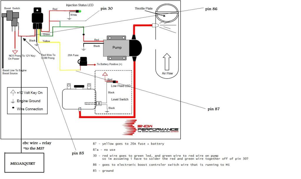
That's a common automotive-style SPDT relay. It's upside-down in your picture, but you can see the terminal numbers molded into the bottom cover.
Here's a diagram of what the terminals do, in physical and schematic form:


Refer to the diagram on page 17 of this manual: http://www.snowperformance.net/produ...ion_pdf-44.pdf
Pins 85 and 86 are the coil, which is what triggers the relay to activate when 12v is applied across it. One of these two pins will go to the vacuum switch COM terminal, the other to ground.
I can't say with absolute certainty how Snow's relay harness is built, however you can follow this scheme and make it work:
Connect pin 87 (N/O) to the 20A fuse that goes to Battery +. This is the equivalent of the yellow wire in Snow's manual.
On pin 30 (common) you're going to have two wires. One will go the LED (red in Snow's manual) and the other will go to the pump (green in Snow's manual).
Pin 87a (N/C) will not be used.
Note that this assumes your vacuum switch is set up such that it does not conduct when in vacuum, and that it does conduct when in boost. If you find that the pump comes on when in vacuum, reverse the N/O and N/C terminals on the vacuum switch.
Here's a diagram of what the terminals do, in physical and schematic form:
Refer to the diagram on page 17 of this manual: http://www.snowperformance.net/produ...ion_pdf-44.pdf
Pins 85 and 86 are the coil, which is what triggers the relay to activate when 12v is applied across it. One of these two pins will go to the vacuum switch COM terminal, the other to ground.
I can't say with absolute certainty how Snow's relay harness is built, however you can follow this scheme and make it work:
Connect pin 87 (N/O) to the 20A fuse that goes to Battery +. This is the equivalent of the yellow wire in Snow's manual.
On pin 30 (common) you're going to have two wires. One will go the LED (red in Snow's manual) and the other will go to the pump (green in Snow's manual).
Pin 87a (N/C) will not be used.
Note that this assumes your vacuum switch is set up such that it does not conduct when in vacuum, and that it does conduct when in boost. If you find that the pump comes on when in vacuum, reverse the N/O and N/C terminals on the vacuum switch.
Reply
0
0
02-12-2010, 06:32 PM
#16
Junior Member
Thread Starter
iTrader: (1)
Join Date: May 2009
Location: Niagara Falls, ON
Posts: 431
Total Cats: 2
That's a common automotive-style SPDT relay. It's upside-down in your picture, but you can see the terminal numbers molded into the bottom cover.
Here's a diagram of what the terminals do, in physical and schematic form:
Refer to the diagram on page 17 of this manual: http://www.snowperformance.net/produ...ion_pdf-44.pdf
Pins 85 and 86 are the coil, which is what triggers the relay to activate when 12v is applied across it. One of these two pins will go to the vacuum switch COM terminal, the other to ground.
I can't say with absolute certainty how Snow's relay harness is built, however you can follow this scheme and make it work:
Connect pin 87 (N/O) to the 20A fuse that goes to Battery +. This is the equivalent of the yellow wire in Snow's manual.
On pin 30 (common) you're going to have two wires. One will go the LED (red in Snow's manual) and the other will go to the pump (green in Snow's manual).
Pin 87a (N/C) will not be used.
Note that this assumes your vacuum switch is set up such that it does not conduct when in vacuum, and that it does conduct when in boost. If you find that the pump comes on when in vacuum, reverse the N/O and N/C terminals on the vacuum switch.
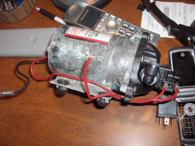
Also the red wire runs to the back of back of the pump goes into it looks like a switch and another red comes out, i know i use the red one for pin 30 but whats the point of routing it to the back? Is it some type of switch for the pump?
Reply
0
0
02-12-2010, 08:26 PM
#17
Sorry I missed the updates here...but looks like they helped you.
I had hell, thinking I'd wired the relay wrong, but turns out I had a dead on arrival Nason pressure switch.
I have no idea about the red pump wire, but they all do that. Likely needs to power both the motor and some internal switch. You just need power to that one wire.
EDIT: Also, you can try the DevilsOwn forum, they'll help you out even if you didn't get the kit from them. Awesome guys, good advice, just sometimes slow responses.
Reply
0
0
02-13-2010, 01:39 PM
#18
Boost Pope
iTrader: (8)
Join Date: Sep 2005
Location: Chicago. (The less-murder part.)
Posts: 33,339
Total Cats: 6,793
Unfortunately, Windows 7 won't run it (this is the first app I've come across this problem with) and while it does work in virtual XP mode, I decided it'd be a good time to upgrade to the current version and learn new things.
Holy freaking ****- when did PSP turn into a Photoshop-wannabe? The whole reason I used to love it was because it was simple! No layers, no vector BS, just a plain ole' bitmap editor... Took me forever just to figure out how to draw a straight line. You'd think it was the icon with a picture of a line on it, right? No, it's the one with a picture of a fountain pen. That's how you draw a straight line in PSP9.
Anyway, here's how you'll wire it, assuming your MS already has a relay drive built in. Note that this is NOT the correct wiring if you intend to use the MS to do PWM control, only for simple on/off control.

Reply
0
0
02-13-2010, 02:46 PM
#19
Junior Member
Thread Starter
iTrader: (1)
Join Date: May 2009
Location: Niagara Falls, ON
Posts: 431
Total Cats: 2
Sorry for my tardiness. Normally I just fire up PaintShop Pro, of which I have been continuously using version 4 since the mid '90s.
Unfortunately, Windows 7 won't run it (this is the first app I've come across this problem with) and while it does work in virtual XP mode, I decided it'd be a good time to upgrade to the current version and learn new things.
Holy freaking ****- when did PSP turn into a Photoshop-wannabe? The whole reason I used to love it was because it was simple! No layers, no vector BS, just a plain ole' bitmap editor... Took me forever just to figure out how to draw a straight line. You'd think it was the icon with a picture of a line on it, right? No, it's the one with a picture of a fountain pen. That's how you draw a straight line in PSP9.
Anyway, here's how you'll wire it, assuming your MS already has a relay drive built in. Note that this is NOT the correct wiring if you intend to use the MS to do PWM control, only for simple on/off control.

Reply
0
0
02-13-2010, 09:32 PM
#20
Boost Pope
iTrader: (8)
Join Date: Sep 2005
Location: Chicago. (The less-murder part.)
Posts: 33,339
Total Cats: 6,793
Ok, I guess I need to take a step back here.
There are two fundamental ways to do WI with the MS.
Way #1 involves using a high-speed solenoid (such as the one sold by AquaMist) which is pulsewidth modulated by the MS just like a fuel injector. When the MS wants to inject, it does two things- turn on the pump, and start driving the solenoid. Thus, you have two outputs of the MS to deal with, a relay driver to power the pump, and a PWM driver to power the solenoid. Here's the MS documentation on this mode: MSnS-Extra Hardware Manual
Way #2 is far cheaper, and sounds like what you're shooting for based on the list of hardware you've given. It consists of half of the circuit from the above example- the relay driver.
This is nothing more than a transistor wired to a pin of the CPU on one side, and a terminal of the DB37 connector on the other. Since the CPU itself is not capable of sinking enough power to drive a relay, we use the transistor to do that job. All you do is set that output to come on above a certain MAP, and that's it. There's no control over the quantity of water being injected, it's just on or off like the basic Snow circuit we've shown above.
Here's the documentation on general purpose relay driver outputs: MSnS-Extra Hardware Manual
Reply
0
0


