
Water Injection and EMU?

 hehehe, that will be my my next move after i get all the turbo stuff worked out
  08-22-2007, 02:23 AM
#22

I'm the master of PWM. What do you need? I can draw up something. Motor control? Solinoid control?
Oh! Which reminds me... I found the perfect little solinoid valve for the junkyard do-it-yourself'er. You can find on a Chevy Lumina van that has the airpump built in for filling tires. Open the rear cargo door and check the left rear compartment behind the controll panel for the pump. There's a spiffy little high pressure solinoid back there.
 I'll post a pic.
I think 10hz would be more then enough. Put the solinoid in the trunk and the line to the intake will 'buffer' the pulsation.

Reply
 0
0

0
08-22-2007, 08:58 AM
#23
Boost Pope


iTrader: (8)
Join Date: Sep 2005
Location: Chicago. (The less-murder part.)
Posts: 33,339
Total Cats: 6,793
What can I say? He's still wrong. PWM attempts to emulate an analog signal using only a digital switch. Fuel injector drivers, by comparison, are not trying to feed a variable voltage to the injectors to hold them in an intermediate-state condition, they're just turning 'em on and off. The components may look similar, but the application defines the circuit. 
The only way I'd call a fuel-injector driver a PWM circuit would be in a peak-hold application, and only if the "hold" condition was achieved by high-speed switching of the driver, rather than with a resistor.
And what the heck is a solinoid, anyway... :gay:
The only way I'd call a fuel-injector driver a PWM circuit would be in a peak-hold application, and only if the "hold" condition was achieved by high-speed switching of the driver, rather than with a resistor.
And what the heck is a solinoid, anyway... :gay:
Last edited by Joe Perez; 08-22-2007 at 09:11 AM.
Reply
0
0
 08-22-2007, 04:24 PM
#25
Supporting Vendor

iTrader: (33)
Join Date: Jul 2006
Location: atlanta-ish
Posts: 12,659
Total Cats: 134
once again Lazzer talks out his ***
Lazzer, I'll agree with you that the concept between fuel injector driver and pulse width modulation are similar. However, the applications are completely different.
PWM is a method digital regulation to achieve "analog-like" results. Most common application is voltage control (dimmer or motor speed control).
A fuel injector is simply turning on and off.

Reply
0
0
08-22-2007, 04:28 PM
#26
Supporting Vendor
iTrader: (33)
Join Date: Jul 2006
Location: atlanta-ish
Posts: 12,659
Total Cats: 134
The device needs to begin at 50% duty cycle, ramp up over 3 seconds, then remove itself from the fan circuit. No fan shut off regulation required.
Reply
0
0
08-22-2007, 04:46 PM
#28
Do you consider .0001ohm of a mosfet "removed" or do you need a bypass relay to activate once 100% is reached? The program I use to draw schematics doesn't have any pwm driver IC models. One I use is the 3525. There are a few ways to do this. If you want exactly 3 seconds you'll need a pic processor otherwise I'll go with an RC network similer to a throttle ramp in motor control. Will that be enough for you?
Reply
0
0
08-22-2007, 04:56 PM
#30

Back when I was screwing around designing a speed control for my EV I wondered how well the circuit would work for audio as a "class-d" amplifier. In the video it's just one mosfet being used LC coupled to the speaker. The scope is showing the signal at the speaker and is far from ideal. I wasn't building an amplifier after all. I was building a speed control for a 144vdc series wound motor.
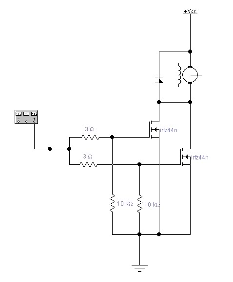
There's the switching side of the fan controller. Ignore the stator winding. That's the only motor model I have.
I guess I can use a dual op-amp for osc and pwm. bbl
Reply
0
0
08-22-2007, 04:59 PM
#31
Junior Member

Join Date: Nov 2005
Location: Athens
Posts: 197
Total Cats: 0
Sounds like your after the same system i'm running.
I've got the DO base system, running to a Aquamist HSV that i'm controlling via the sub I/J map.
Been running this system for a while now, nothing but praise for it.
The beauty of this system is you can control the HSV and water level by 0.5% DC.
Here's 1 of my sub I/J maps i was running as an example:

Cheers
Mark
I've got the DO base system, running to a Aquamist HSV that i'm controlling via the sub I/J map.
Been running this system for a while now, nothing but praise for it.
The beauty of this system is you can control the HSV and water level by 0.5% DC.
Here's 1 of my sub I/J maps i was running as an example:
Cheers
Mark
Reply
0
0
08-22-2007, 05:00 PM
#32
Supporting Vendor
iTrader: (33)
Join Date: Jul 2006
Location: atlanta-ish
Posts: 12,659
Total Cats: 134
I want the ramp up circuit completely removed from the fan's current path in all ways, once the ramp event is concluded. 3 seconds was a number I pulled out of my ***. It doesn't have to be exact, nor does it have to be exactly regulated.
I also forgot to mention, the parts need to be cheap, and the circuit easy for a novice to build. I have one in mind; I'd be interested to see what you can come up with.
And I can't see you schooling Mr. Joe Perez, Ph.D on circuit theory.
I also forgot to mention, the parts need to be cheap, and the circuit easy for a novice to build. I have one in mind; I'd be interested to see what you can come up with.
And I can't see you schooling Mr. Joe Perez, Ph.D on circuit theory.
Reply
0
0
08-22-2007, 05:23 PM
#33
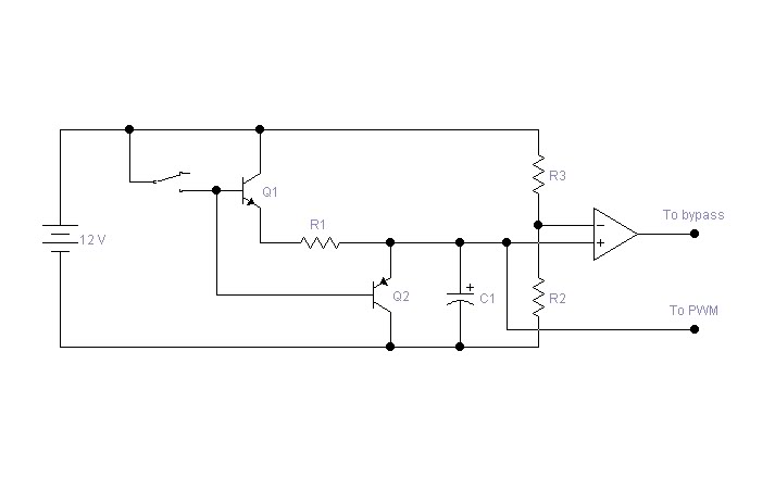
When the switch is closed Q1 will conduct charging C1 thru R1. The voltage on C1 will be sent to the 3525 input to begin 0-100% pwm. When the switch is opened Q2 will discharge C1 to 'reset' the timing portion of the circuit. R2 and R3 set the trip point for the comparator which will be used to activate a bypass relay. I believe the 3525 uses 0-2.5v = 0-100% so the comparator should be adjusted for >2.5v trip in order to activate after 100% pwm is obtained. I'm not going to illustrate a complete schematic or values. That involves time I'm not being paid for. If you use an opamp for your osc/pwm I suggest you use another totempole for the mosfet gate drive.
Reply
0
0
08-22-2007, 05:37 PM
#34
I wasn't aiming on "schooling" anyone. I'm just saying injector drive is PWM. Hence the "duty cycle" term used in fuel injection. The duty cycle is the "on" state of the pulse or "pulse width". The ecu adjusts (modulates) the pulse width bassed on engine load and that, by definition, is pulse width modulation. PWM
Reply
0
0
09-12-2007, 10:51 PM
#37
Junior Member

Join Date: Aug 2005
Location: Iowa
Posts: 338
Total Cats: 0

You've been schooled.
Reply
0
0
09-12-2007, 10:58 PM
#38
Junior Member
Join Date: Aug 2005
Location: Iowa
Posts: 338
Total Cats: 0
I think there is a simpler solution, if you run a vacum line to your container, then the more you boost the more you build pressure in the container pushing water/methanol to your nozzle. A check valve can be used so water only goes in the intake manifold when boost is present and not vac. Container must be pressure tested before trying this method but there are no electronics nor moving parts that will fail. Just an input...
Reply
0
0


