VVT angle oscillates at idle
#1
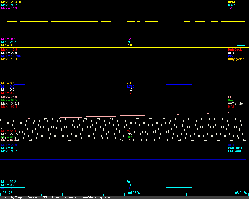
Got a weird issue that stopped me from getting my VVT working over the summer. At idle the VVT angle reading oscillates between 277 and 295 degrees. If I try to enable PID control of the cam the idle goes to **** while the MS tries to figure out what is going on.
Not sure why it is happening or any idea on what I could have fucked up to cause it. Motor is a 2005, shell is a 1997. VVT is controlled over the IAC wires. Car runs otherwise fine, have about 13 hours on the motor currently.
I attached the msq and a quick data log showing it. Also a picture of it happening for the low effort crowd. Now I know the reading is at least somewhat right because I killed the motor by setting the test duty cycle to 99 and the log shows that the cam advanced.

#2
Joined: Jun 2005
Posts: 19,338
Total Cats: 574
From: Fake Virginia
set your vvt target to 0 at idle.
edit:
nevermind that. you have to set your minimum and maximum angles or the target will be meaningless.
0. create gauges on the dashboard for VVT angle 1.
1. enable the test output.
2. set test output duty to 0%
2b. start the car.
3. look at the VVT angle 1 and write it down. note this as "minimum".
4. open up the VVT dialog again and hold your RPM at 2000
5. set the vvt duty to 100%
6. look at the VVT angle 1 and write it down. note this as "maximum".
7. turn off the car and enter these values in the min and max fields.
disable VVT test output
disable Use Hold Duty.
start up.
#3
It is. Using the table you posted in the ms3efi VVT thread. Also running test mode with duty set to 0 in that log. I get the same odd readings if I pull the plug out of the VVT solenoid as well.
e:
I'll try that process again tomorrow. The last time I tried it (a few months ago) I didn't get a single value under step 3. Can't remember if I got a single value for the max either. Let me see if I can find a datalog.
e:
I'll try that process again tomorrow. The last time I tried it (a few months ago) I didn't get a single value under step 3. Can't remember if I got a single value for the max either. Let me see if I can find a datalog.
Last edited by FatKao; 11-13-2011 at 10:30 PM.
#5
Nothing, car idles/runs perfectly unless I manually advance the cam with test duty (stalls as expected) or enable PID control, then idle oscillates badly and the motor eventually stalls. I highly doubt that what the MS3 is indicating is the reality of the cam. I can only get one trace on my scope though so I can't easily verify. I might have to go and buy a new set of test leads if I can't figure out why this is happening.
Last edited by FatKao; 11-14-2011 at 12:23 PM. Reason: clarity
#7
I think I may have figured out what the issue is. I have my trigger set to rising edge. It seems that the other stuff I see from 01+ Miatas is falling edge.
Do you guys have falling edge as well? And I can't get the car to start if I change from rising to falling edge. Any ideas on what I would have to change other than the offset to get it going properly? MSQ is still the same as the one in the OP for all meaningful values.
Didn't mention it in here but 2005 motor in a 1997 shell. MS3 w/MS3x for cam in.
e:
Upgraded from alpha 11 to alpha 18 and it didn't fix it.
#9
I don't have a log to prove the point but I'm 99% certain it happens when the engine is up to temp as well.
I was going to pull off the valve cover so I could take off the top timing belt cover so I could verify the cam timing was static with a timing gun but it got a bit cold and I noticed the falling vs rising edge thing so I stopped.
I was going to pull off the valve cover so I could take off the top timing belt cover so I could verify the cam timing was static with a timing gun but it got a bit cold and I noticed the falling vs rising edge thing so I stopped.
#11
Found your thread on ms3efi about the MAX9926. Should falling edge be used with the normal MS3 inputs as well or is that just a consequence of using the MAX9926 inputs?
I also posted a thread over at ms3efi, pretty much the same info there as here.
http://www.msextra.com/forums/viewto...?f=125&t=44120
I also posted a thread over at ms3efi, pretty much the same info there as here.
http://www.msextra.com/forums/viewto...?f=125&t=44120
#13
Ok. I can reproduce this on the stim as well. I'm thinking it is likely something wrong with one of my input circuits. Does that make any sense?
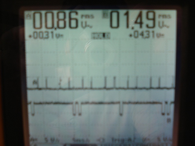
Does this look right? I would think that both signals should go to +5v or -5v. Sorry for the ---- quality, the guy who had this scope before me lost the $200 cable to connect it to a PC. This is taken from the CPU pins.

Does this look right? I would think that both signals should go to +5v or -5v. Sorry for the ---- quality, the guy who had this scope before me lost the $200 cable to connect it to a PC. This is taken from the CPU pins.

Last edited by FatKao; 02-26-2012 at 05:20 PM.
#15
OP: Did you find a solution?
I came across a similar problem where the VVtangle gauge was oscillating by more than 30 degrees, coupled with a high rpm sync loss. I found that my crank sensor gap was ~1/4" and I was running on rising edge. I closed the gap, then the car wouldn't sync. Switched to falling edge, and it ran perfectly after resetting timing. VVT worked correctly. I'm running Abe's input circuits on the mainboard.
It is possible for the motor to run on rising or falling edge with the same configuration, if your crank sensor gap is too large.
#16
I think my issue boils down to noise/bad grounds. I just double checked my crank gap since I have my intake 1/2 off already and it's good. When I flip to falling edge I get a ton of missed triggers. Putting my scope on the raw inputs from the sensors they are less than perfect, honestly a bit surprised they work at all. My input circuits are the MS3X cam in and V3 board opto as per the wiki.
The VVT jumpyness while running on rising edge seems like some kind of bug in the code since I haven't seen it in any electrical signal I've looked at. However I'm pretty sure that rising edge won't work for a VVT anyway motor since the cam tooth will cross a crank tooth while at full advance.
But the weather is nice now, already had an AX, have race this week and a DE the week after that so it'll likely be mid-summer when things slow down enough for me to start dicking around with it again. I'll likely switch over to Abe's NB input circuit and see if I can get a clean signal on falling edge.
Thread
Thread Starter
Forum
Replies
Last Post
StratoBlue1109
Miata parts for sale/trade
21
09-30-2018 02:09 PM
JesseTheNoob
DIY Turbo Discussion
15
09-30-2015 03:44 PM


