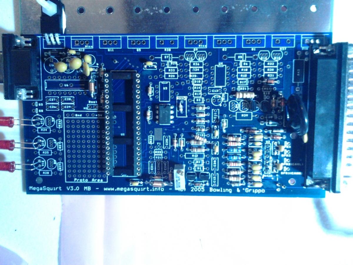
Upgrade Time
#2
I suppose you will be using MS3X for full sequential. If this is the case then you only need jumpers from s12 to js9, from tachselect to vrin, and from vrout to tsel. You are missing some components for the vr ckt on the mainboard such as r52 and r56. The cas input needs a pullup resistor. MS3X also handles spark, ebc, and pwm idle so you don't need those circuits on the mainboard.
Read here: http://www.msextra.com/doc/ms3/build_manual.html
Read here: http://www.msextra.com/doc/ms3/build_manual.html
#7
Thread Starter
Joined: Sep 2008
Posts: 883
Total Cats: 56
From: Tucson, Arizona
yeah i have the expander board too.
will remove. check. now i need to find r56 or an alternative. I should have just sold this thing and bought a new kit. i feel like it's more work to review my board then it is to build a fresh one.
will remove. check. now i need to find r56 or an alternative. I should have just sold this thing and bought a new kit. i feel like it's more work to review my board then it is to build a fresh one.
#10
Remove iac1a to js10, remove the pullup resistor at js10, and remove the cap.
The complete vr ckt for the crank input requires adding some resistors, two caps, two transistors, and a diode.
Specifically add r42, r44, r45, r46, r47, r48, r50, r51, r53, r54, r55, c31, c32, d24, q22, q23, and as mentioned earlier the trim pots r52 and r56.
FRT's board has a modified vr ckt from Brain's/Frank's writeup.
#16
Thread Starter
Joined: Sep 2008
Posts: 883
Total Cats: 56
From: Tucson, Arizona
haha what's the sigh for scott?
I jumped vrin & tachselect, tsel & vrout. Just have to make the vr circuit now i think?
I haven't really touched my ms since i made it. Everything made so much more sense then... I feel like a re-re touching this thing now.
I jumped vrin & tachselect, tsel & vrout. Just have to make the vr circuit now i think?
I haven't really touched my ms since i made it. Everything made so much more sense then... I feel like a re-re touching this thing now.
#17
Because instead of removing all your wiring and extra circuits and adding 20 components, you could have pulled your MS1 CPU, added the MS3 CPU and moved two wires on the underside and been running MS3.
BUT, I do think since you have the expander it wouldn't be a bad idea to remove all your add on circuits and just run them off the expander.
AND you don't need the VR input circuit. You could the crank signal running through the opto circuit, run the cam in the expander, and be good to go. I see no reason to add the VR circuit in this case.
things I'd move to the expander:
spark outputs
fuel outputs
fuel pump (going to 2O, not using high side driver)
the three relays you have on the proto
idle control
#18
Thread Starter
Joined: Sep 2008
Posts: 883
Total Cats: 56
From: Tucson, Arizona
That sounds good to me. If i don't need to build the VR ckt then I don't need any additional components correct? I'm going to be near the electronics store which is clear across town. (30-45min) Is there anything I need while i'm out?
I'm going to setup the opto circuit again for crank and run the rest off the expander. Sounds the easiest to me.
I'm going to setup the opto circuit again for crank and run the rest off the expander. Sounds the easiest to me.


