
Syncs on stim, not on car. 2001 miata.
 11-28-2010, 09:54 AM
#1
DEI liberal femininity


Thread Starter
iTrader: (8)
Join Date: Jun 2005
Location: Fake Virginia
Posts: 19,338
Total Cats: 574
(this is cross-posted to the msextra forums)
I'm finishing my MS3X and thought I got it all sorted out but something is wacky.
My crank and cam inputs are based on the MAX9926 reference circuit.
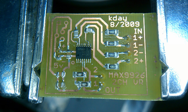
The crank and cam signals go into the IN+. The IN- are grounded.
With the Stim set up to 99-00 miata and the MS trigger set up to same and rising edge, I get perfect sync.

If I change the trigger to falling edge, it still syncs but (and here's the crazy part) when I start the composite logger, it IMMEDIATELY loses sync. Stop the comp logger, it syncs right away.

Now... when I put the thing in the car and hook it up to the actual sensors, I get varying results. First of all, I can't get a good composite log that looks anything like the above images unless I unground the IN- (I understand that leaving them floating enables auto threshold on the 9926?) and stick a pullup resistor on the raw input (2.2k to VCC before the 9926 1k input resistor).
But what's crazy is that while the signals look ok, I get no sync at all.

So a few questions I was trying to answer for myself:
* does the crank and cam input need a pullup resistor?
* does the 9926 really automatically set the threshold when the IN- are floating?
* in TunerStudio, should the tooth spikes point up or down to be "right"?
* do any of the settings in Ignition Options/Wheel Decoder affect the ability to sync (other than spark mode or input capture)?
I searched a lot for some concrete answers to the 99-2005 miata triggers and only found 12 page threads arguing if the sensors were either broken or hall or VR or sticky. I'd like to avoid all those conversations again. I understand that the signals should be 5V on gaps and 0V on teeth and trigger on the RISING edge which is the 0-5V-going edge because that edge never "sticks" at various RPM and remains between adjacent crank teeth for the entire range over which the VVT works.
Thanks for the help.
Matt
I'm finishing my MS3X and thought I got it all sorted out but something is wacky.
My crank and cam inputs are based on the MAX9926 reference circuit.
The crank and cam signals go into the IN+. The IN- are grounded.
With the Stim set up to 99-00 miata and the MS trigger set up to same and rising edge, I get perfect sync.
If I change the trigger to falling edge, it still syncs but (and here's the crazy part) when I start the composite logger, it IMMEDIATELY loses sync. Stop the comp logger, it syncs right away.
Now... when I put the thing in the car and hook it up to the actual sensors, I get varying results. First of all, I can't get a good composite log that looks anything like the above images unless I unground the IN- (I understand that leaving them floating enables auto threshold on the 9926?) and stick a pullup resistor on the raw input (2.2k to VCC before the 9926 1k input resistor).
But what's crazy is that while the signals look ok, I get no sync at all.
So a few questions I was trying to answer for myself:
* does the crank and cam input need a pullup resistor?
* does the 9926 really automatically set the threshold when the IN- are floating?
* in TunerStudio, should the tooth spikes point up or down to be "right"?
* do any of the settings in Ignition Options/Wheel Decoder affect the ability to sync (other than spark mode or input capture)?
I searched a lot for some concrete answers to the 99-2005 miata triggers and only found 12 page threads arguing if the sensors were either broken or hall or VR or sticky. I'd like to avoid all those conversations again. I understand that the signals should be 5V on gaps and 0V on teeth and trigger on the RISING edge which is the 0-5V-going edge because that edge never "sticks" at various RPM and remains between adjacent crank teeth for the entire range over which the VVT works.
Thanks for the help.
Matt

Reply
 0
0

0
 11-30-2010, 09:40 AM
#10
DEI liberal femininity
Thread Starter
iTrader: (8)
Join Date: Jun 2005
Location: Fake Virginia
Posts: 19,338
Total Cats: 574
The wiring diagram shows that the cam and crank sensors both get power from "D" which is 12V from the main relay. It doesn't go back to the harness.
The other two connections are:
1. 4A "Device GND"
and
2. 3V and 3Y (cam and crank signal respectively).
Then later it shows how to inspect the signals...
Note the nice consistency of using 2V/Div for the cam (it is 2.5 squares high) and 1V/Div for the crank (it is 5 squares high) so both are normally 5V and a tooth brings them to 0. At least Mazda thought so in the FSM.
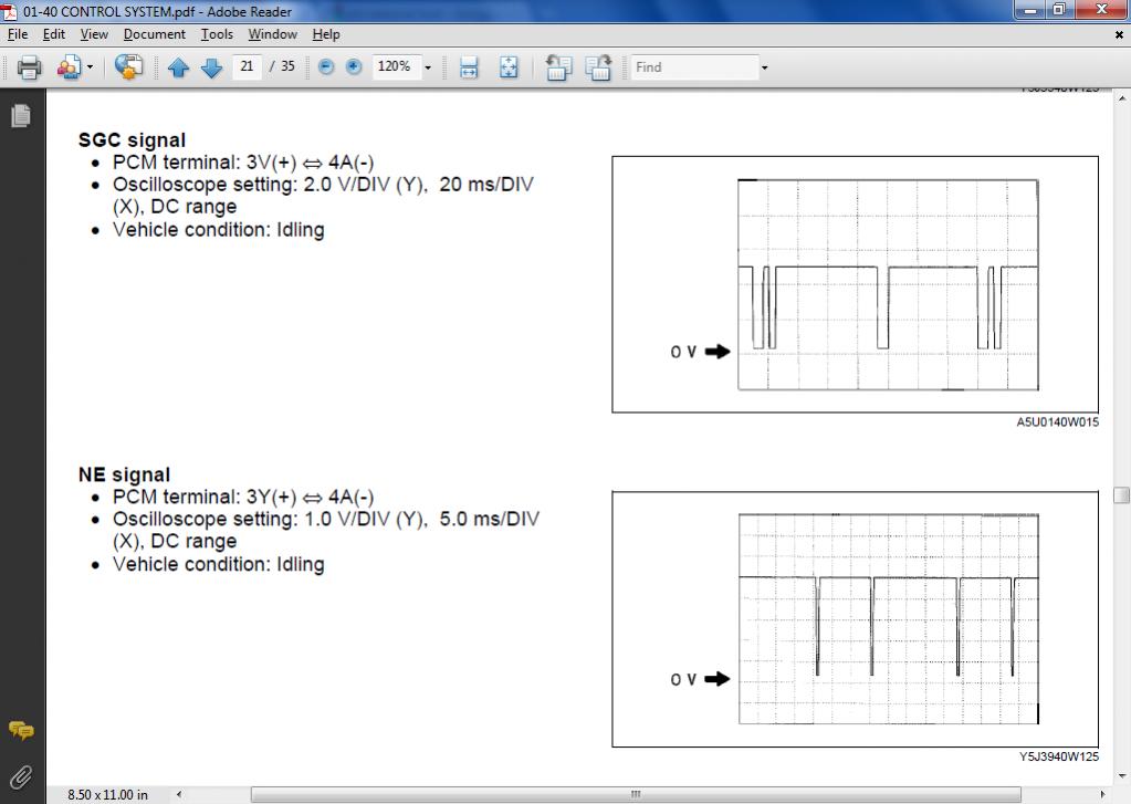
And these are measured at the ECU pins so they are straight out of the sensors. The only augmentation would be a 5V pullup to get full scale.
The other two connections are:
1. 4A "Device GND"
and
2. 3V and 3Y (cam and crank signal respectively).
Then later it shows how to inspect the signals...
Note the nice consistency of using 2V/Div for the cam (it is 2.5 squares high) and 1V/Div for the crank (it is 5 squares high) so both are normally 5V and a tooth brings them to 0. At least Mazda thought so in the FSM.
And these are measured at the ECU pins so they are straight out of the sensors. The only augmentation would be a 5V pullup to get full scale.
Reply
0
0
11-30-2010, 11:00 AM
#14
Supporting Vendor

iTrader: (33)
Join Date: Jul 2006
Location: atlanta-ish
Posts: 12,659
Total Cats: 134
Matt,
Do you have pullups between the sensors and 9926? I'd think you'd need 470 ohm 5v pullups. I'd probably also try disconnecting IN- and let the chip auto threshold. If that doesn't work, I'd hook IN- to ~2.5V, but not to ground.
Sorry, don't have a lot of hands on with the 9926 yet.
Do you have pullups between the sensors and 9926? I'd think you'd need 470 ohm 5v pullups. I'd probably also try disconnecting IN- and let the chip auto threshold. If that doesn't work, I'd hook IN- to ~2.5V, but not to ground.
Sorry, don't have a lot of hands on with the 9926 yet.

Reply
0
0
11-30-2010, 11:04 AM
#15
Boost Czar

iTrader: (62)
Join Date: May 2005
Location: Chantilly, VA
Posts: 79,751
Total Cats: 4,127
IIRC there's just a 5v and ground going into that chip. But the output is going directly from the chip to JS10. Matt, like Ben suggests, try a 5v pullup through a 470ohm to js10 as well.
But it looks like the outputs get a 5v pull-up through the two resistors with the 1001 stamped on them.
But it looks like the outputs get a 5v pull-up through the two resistors with the 1001 stamped on them.
Reply
0
0
11-30-2010, 11:31 AM
#17
Boost Pope
iTrader: (8)
Join Date: Sep 2005
Location: Chicago. (The less-murder part.)
Posts: 33,497
Total Cats: 6,905
Yes, if you want to use a 9924 / 9926 with an OEM sensor, you need to leave the chip's (-) input floating (do not ground it), and apply a 5v pullup through a resistor (eg: 1k) to the (+) input. This will cause the threshold to auto-set at 2.5v. I've only personally run the 9924 with an actual VR sensor, however I'm taking this info from a conversation with Jean B�langer here: http://www.msextra.com/forums/viewto...35149&start=20
Now, I'll admit that I know next to nothing about the composite logger (I'm still stuck in MS1 land, where it's fairly useless) but am I the only one who thinks that the first and third traces posted in the first post do not show similar-looking data? The first one (working on stim) shows me 4 CKPs per 1/2 cam revolution, whereas the last one (not working, on car) doesn't.
EDIT:
It also appears (in the last picture) that the yellow trace (which is labeled PriLevel) is depicting the cam sensor. Have you, by chance, accidentally wired CMP and CKP backwards?
Reply
0
0
11-30-2010, 11:16 PM
#19
DEI liberal femininity
Thread Starter
iTrader: (8)
Join Date: Jun 2005
Location: Fake Virginia
Posts: 19,338
Total Cats: 574
Wiring-wise, IN1 definitely comes from main harness pin 24 (crank) and out 1 goes to TSEL.
Similar for IN2/Cam/Out 2/JS10.
If the Stim can generate a sync-able signal via the 9926 circuit, then the output of the 9926 should not be the problem. The 9926 simply follows the input and generates the same output at full amplitude, right?
This leads me to believe the problem is somewhere between my crank and cam sensors and the 9926. Since I dont know what the stim is generating, I dont know what I dont have on the car that is present on the stim for sync to take place.
Reply
0
0
12-06-2010, 03:42 PM
#20
DEI liberal femininity
Thread Starter
iTrader: (8)
Join Date: Jun 2005
Location: Fake Virginia
Posts: 19,338
Total Cats: 574
Here's the latest update (note there's more at my thread on msextra):
This is my lovely cam and crank signal (cam on top) during cranking. Note that I can't do a "real scope trace" while the car is running because this particular capture requires the trigger setting to be changed to "log crank & cam" instead of "miata 99-00".

I reconstructed the signals based on lots of searching and photoshoppery:

Now I'm pretty sure I'm using the pink edges for my triggers. If it's not clear in the fucked up plot, they are the rising edges. And they appear to be in the right place in spite of the yellow falling edges (also known as "bonkers", "stuck" or whatever...).
My problem is that even with this set up properly with the proper edges, the car runs like ****. The timing (when set to fixed timing) is all over the place.
suggestions or comments?
This is my lovely cam and crank signal (cam on top) during cranking. Note that I can't do a "real scope trace" while the car is running because this particular capture requires the trigger setting to be changed to "log crank & cam" instead of "miata 99-00".
I reconstructed the signals based on lots of searching and photoshoppery:
Now I'm pretty sure I'm using the pink edges for my triggers. If it's not clear in the fucked up plot, they are the rising edges. And they appear to be in the right place in spite of the yellow falling edges (also known as "bonkers", "stuck" or whatever...).
My problem is that even with this set up properly with the proper edges, the car runs like ****. The timing (when set to fixed timing) is all over the place.
suggestions or comments?
Reply
0
0


