
Started my MS3X build this week, questions to follow
 03-29-2012 | 06:56 PM
#1

I started my Megasquirt build this week. I have been reading for the last few months and decided the MS3x was what I wanted for my '99 nb. I figured I could start a thread to fill in some of the gaps for anybody else thinking about MS3x DIY.
I am still a little in the dark because it is hard to wrap your head around all of the variables associated with inputs and outputs without a finished MS in front of you. For now I am following Frank's (Westfield MX-5) amalgamated instructions on his blog. I am sure that once I have the built board in front of me and I am trying to make it work, some modification/repair will be necessary.
I ordered the parts listed on Frank's build info page. I didn't realize the price of the MS had been slowly creeping upwards. Still a great deal for the money.
Do I need the STIM? I have fancy multimeters, oscilloscope, and a variable power supply- is that enough to fake the signal for testing?
I also bought an Innovate Motorsports LC-1 w/gauge. I will buy tunerstudio when this thing is together.
Ran into my first problems though. I ordered the closed element IAT, which won't work for me. Also, the MS3 doesn't ship with any wire to make a harness, not a big deal but for those placing orders buy some wire while it is convenient. I am going to copy the Tyco connector in the box PNP. Bought the connector from onlinecomponents.
I am still on the first couple steps of building. I am sure I will run into problems soon enough. I'll post them here. The alternator circuit may be challenging to fit in the smallest space possible on the proto area. I will be working on it a couple hours a night after work so it should be done by the end of next week, hopefully.
One more question, on the instructions it says U5 should be mounted with a plastic screw, but later the MS3x gets mounted to this spot using a metal screw+standoff? Can anyone who has been there before shed some light on this?
Reply
 0
0

0
03-29-2012 | 10:54 PM
#2
I needed to check the power supply voltages without a Stim and it took a little while to piece everything together so here is a step by step for how to test your voltages.
Hook up 9V DC, with lowest amperage possible (<300ma). You only need voltage and too many amps can kill improperly installed components.
On the DB37 use pin 28 for +, use pin 19 for GND.
Check U1 pins for proper voltages, pin 1 is closest to C19, 40 is adjacent to 1.
GNDs 2/19/32
5V 1/20/31
Also check pin 16 against GND for ~9 volts to check jumper.
Reply
0
0
 03-30-2012 | 01:30 PM
#4
Thanks for the heads up on the daughterboard standoff. I ended up finding the directions for this but it was hard to tell from the pictures I found if the screw needed to be plastic or metal.
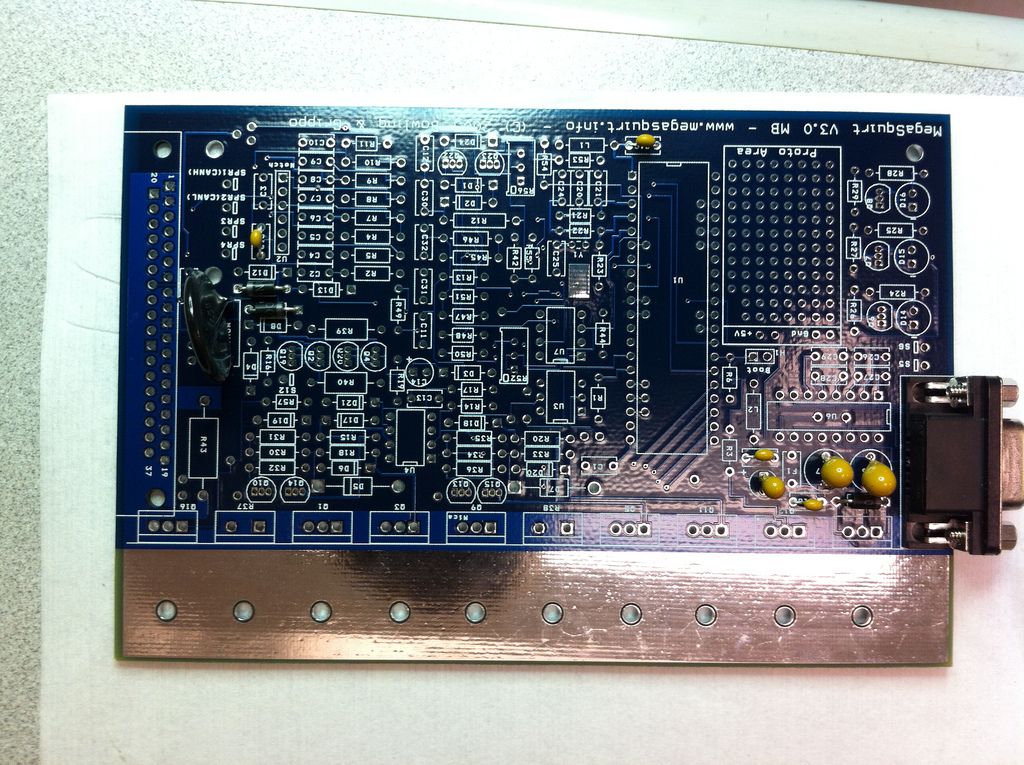
Here is a gratuitous photo of current progress, I couldn't find that many pictures of MS3/x boards in progress so I figured I would post what I have. Sorry for the skewed image. I used the optical magnifier to get a better focus for the lettering.
Here is a gratuitous photo of current progress, I couldn't find that many pictures of MS3/x boards in progress so I figured I would post what I have. Sorry for the skewed image. I used the optical magnifier to get a better focus for the lettering.
Reply
0
0

 04-03-2012 | 04:39 PM
#7
What is the difference between these two diagrams? I see the difference in wiring, but what is the effect of one version over the other? Is it just preference, or are they two different setups?
https://lh3.googleusercontent.com/-7...52520frank.jpg
https://lh6.googleusercontent.com/-I...00-ECU-MS3.jpg
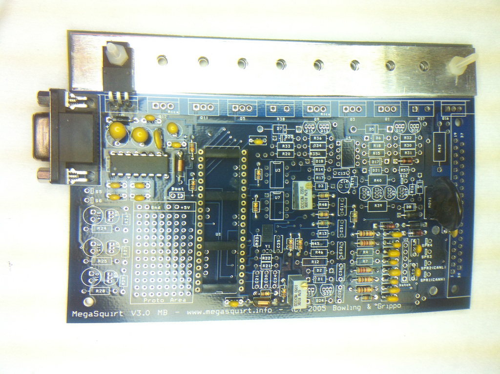
Going on to the alternator circuit, here is the board as of now:
https://lh3.googleusercontent.com/-7...52520frank.jpg
https://lh6.googleusercontent.com/-I...00-ECU-MS3.jpg
Going on to the alternator circuit, here is the board as of now:
Reply
0
0
 04-04-2012 | 06:13 PM
#9
I see now what I was missing, I thought it might have been that but other pins had moved too.
Does anyone have a better photo of the alternator circuit in the Proto area? I will try to make it as small as possible, like Frank's, but for tracing everything out it would be helpful to see a picture. If not I will proceed to prototype board it and take some pictures.
Does anyone have a better photo of the alternator circuit in the Proto area? I will try to make it as small as possible, like Frank's, but for tracing everything out it would be helpful to see a picture. If not I will proceed to prototype board it and take some pictures.
Reply
0
0
04-05-2012 | 12:49 PM
#10

Senior Member
Joined: Nov 2007
Posts: 999
Total Cats: 73
From: Belgium
the Frank one is actually not for publication. It is how I wired my own megasquirt. A couple of pins have moved because I have a euro car (clutch switch and fuel pump are wired different).
Use the other diagram. It has no sequential spark. If you want that, just use 2 free pins for the 2 other spark outputs.
Frank
Use the other diagram. It has no sequential spark. If you want that, just use 2 free pins for the 2 other spark outputs.
Frank
Reply
0
0
04-07-2012 | 11:52 AM
#11
Thanks for clarifying. The walkthrough so far is very easy to follow.
I have been banging my head against the wall with the alternator circuit. I found it only works up to <9 volts. I had to go through the whole circuit and found that I was given a 4.87k resistor instead of a 48.7k. At least it works, now I need to make another trip to the store. Anchor electronics is great if you need a source for parts around Santa Clara.
I have been banging my head against the wall with the alternator circuit. I found it only works up to <9 volts. I had to go through the whole circuit and found that I was given a 4.87k resistor instead of a 48.7k. At least it works, now I need to make another trip to the store. Anchor electronics is great if you need a source for parts around Santa Clara.
Reply
0
0
04-09-2012 | 07:16 PM
#13
I made the switch to the 48.7k and it works! However, I get a shutoff at ~14.15V (Using lab bench power supply and Fluke MM).
Is this too low? I read the spec as <14.4 but I think that must be what the OEM setting?
I have more resistors to try and see which gets me closest to 14.4V. I think the 1% range is working against me right now, I'm off by 1.7%.
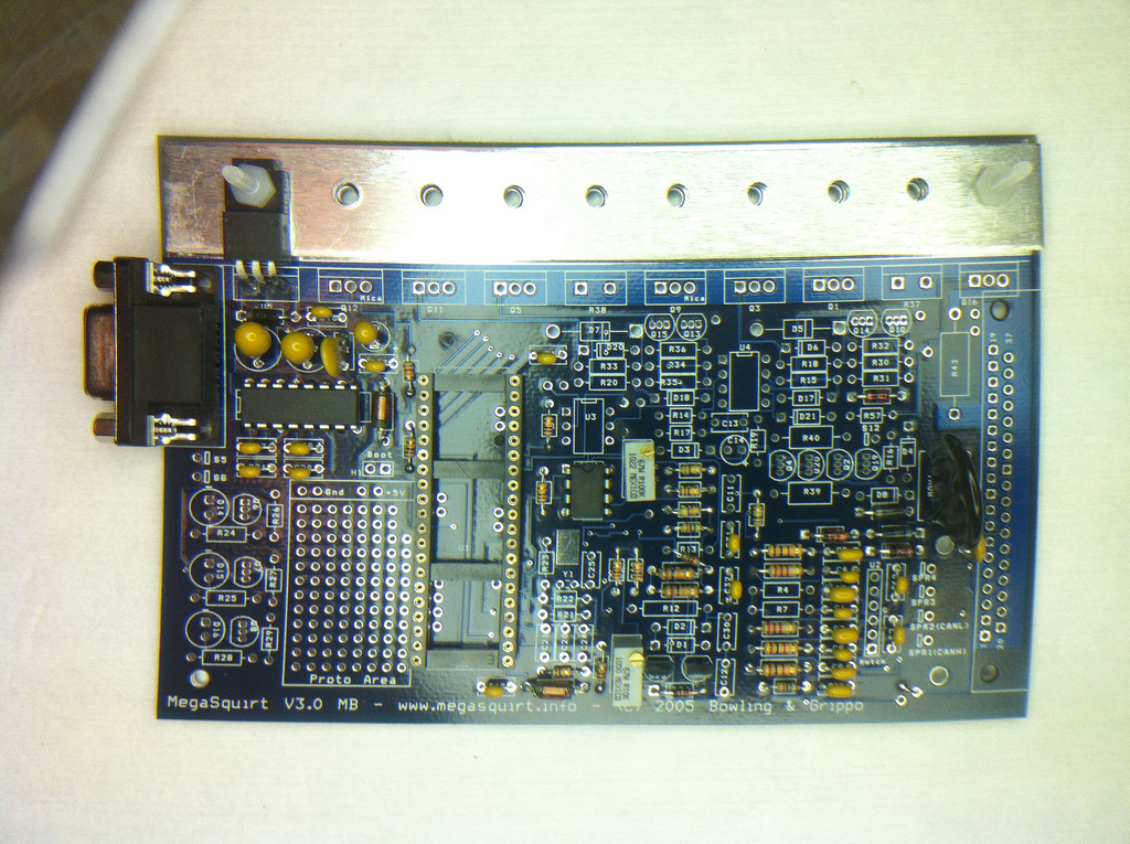
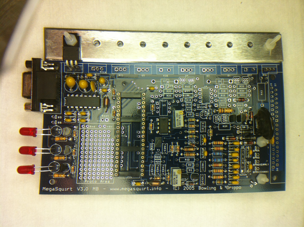
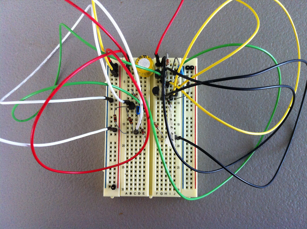
Here is my roughed out proto-board.
Is this too low? I read the spec as <14.4 but I think that must be what the OEM setting?
I have more resistors to try and see which gets me closest to 14.4V. I think the 1% range is working against me right now, I'm off by 1.7%.
Here is my roughed out proto-board.
Reply
0
0
04-09-2012 | 09:03 PM
#15
Any helpful suggestions for cramming the circuit in the proto area? Is this: http://lh4.ggpht.com/-8IMGSlUU_5I/S4...jpg?imgmax=912
a pin by pin guide?
a pin by pin guide?
Reply
0
0
 ).
04-10-2012 | 02:51 PM
).
04-10-2012 | 02:51 PM
#18
Do you have a link to your version? I am open to other options, I even considered using a separate prototyping board.
Like this:http://www.robotshop.com/prototyping...m_campaign=jos
Also, any known problems using a lab power supply to power the unit while I update the firmware? In theory it should be the same as the Stim, minus the inputs. Just use the MS3 DB37 power pin and grounds?
Like this:http://www.robotshop.com/prototyping...m_campaign=jos
Also, any known problems using a lab power supply to power the unit while I update the firmware? In theory it should be the same as the Stim, minus the inputs. Just use the MS3 DB37 power pin and grounds?
Reply
0
0
 04-10-2012 | 03:16 PM
#20
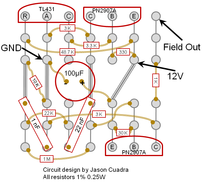
Thin gray lines are copper in the board on DIYPNP boards? The MS PBC I have doesn't have continuity between pins.
Thick gray is jumpered wire? Mustard lines are tails of resistors (confused by the line between resistors 30k and 3k?)?
Am I just reading into it, and this would be a breadboard style layout and it still needs to be adapted to the proto area?
Thick gray is jumpered wire? Mustard lines are tails of resistors (confused by the line between resistors 30k and 3k?)?
Am I just reading into it, and this would be a breadboard style layout and it still needs to be adapted to the proto area?
Reply
0
0


