Second optoisolator on MS2
 04-13-2013, 07:58 PM
#64
Boost Czar


iTrader: (62)
Join Date: May 2005
Location: Chantilly, VA
Posts: 79,607
Total Cats: 4,102
I'm upgrading a MS2 to MS3, decided to add the second opto just as a precaution, although this has been running fine on ms2 since 2008 with just the pull-up on js10.
Last edited by Braineack; 04-14-2013 at 11:12 AM.

Reply
 0
0

0
04-14-2013, 11:12 AM
#65
Boost Czar
iTrader: (62)
Join Date: May 2005
Location: Chantilly, VA
Posts: 79,607
Total Cats: 4,102
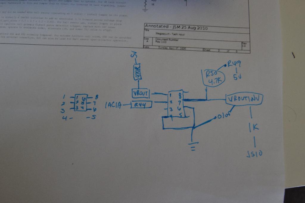
I made a slight error when I built the circuit. I used the wrong hole for r49 so I was sending 5v to ground. I'll post new pics in a sec.
here's what I did:

syncs perfectly.
here's what I did:
syncs perfectly.
Last edited by Braineack; 04-14-2013 at 11:34 AM.
Reply
0
0

 04-15-2013, 08:05 AM
#68
Boost Czar
iTrader: (62)
Join Date: May 2005
Location: Chantilly, VA
Posts: 79,607
Total Cats: 4,102
It was because of you I tried doing it into a preexisting circuit, otherwise I'd have just done it on the proto.
I probably spent a good 2 minutes coming up with it and going gung-ho, I probably could have put more thought into it and made it cleaner, but i just didn't really care that much
I probably spent a good 2 minutes coming up with it and going gung-ho, I probably could have put more thought into it and made it cleaner, but i just didn't really care that much
Last edited by Braineack; 04-15-2013 at 04:38 PM.
Reply
0
0
04-15-2013, 04:53 PM
#70
Junior Member
Thread Starter
iTrader: (1)

Join Date: Sep 2010
Location: Scranton PA
Posts: 264
Total Cats: 4
I used one of these: Dual General-Purpose IC PC Board : PC Boards | RadioShack.com cut in half, and bolted it on to the bottom of the MS board using a previously unused hole in the heatsink.
Reply
0
0


 04-07-2015, 03:49 PM
#78
Newb

Join Date: Jun 2014
Posts: 18
Total Cats: 0
The problem is I am running DIYPNP V1.53B board, so these pins don't apply to me. I couldn't find the schematic for the V1.53B board so its pretty hard to see what is going on. I read somewhere the cam signal is fed directly to the CPU with only pull a 5 volt pullup.
So, I am going to build this on the proto area completely. From what I read so far, I should be able to use this circuit and feed it into the VR2+ the cam input without the pullup to 5V attached to VR2+.
For your convenience. Here is the pin out for DIYPNP board for 95 miata which is what Im driving.
DIYPNP MegaSquirt installation for the Mazda Miata
Reply
0
0


