MEGAsquirt A place to collectively sort out this megasquirt gizmo

Second optoisolator on MS2

Thread Tools
 
Search this Thread
 
Old 02-27-2013 | 02:55 PM
  #1  
duffbuster243's Avatar
Thread Starter
Junior Member
iTrader: (1)
 
Joined: Sep 2010
Posts: 264
Total Cats: 4
From: Scranton PA
Default Second optoisolator on MS2

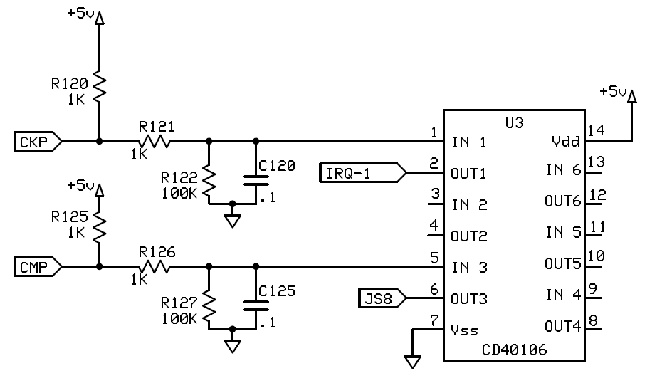
Even after upgrading to MS2 I am still getting a loss of sync or random dropouts, not as often as with MS1 but still enough to annoy me. While looking around I have found what seems to be the end all solution to the problem, which is making a second optoisolator circuit. I have found a diagram posted by Brain floating which I posted along with a picture of it on a board. Please verify that it in fact looks correct.
Attached Thumbnails Second optoisolator on MS2-2ndcas_input.gif   Second optoisolator on MS2-dscf6117g.jpg  
Old 02-27-2013 | 03:19 PM
  #2  
Braineack's Avatar
Boost Czar
iTrader: (62)
 
Joined: May 2005
Posts: 79,818
Total Cats: 4,152
From: Chantilly, VA
Default

is the above yours?


do you have a composite log of your current sync loss?
Old 02-27-2013 | 03:25 PM
  #3  
duffbuster243's Avatar
Thread Starter
Junior Member
iTrader: (1)
 
Joined: Sep 2010
Posts: 264
Total Cats: 4
From: Scranton PA
Default

The above is not mine, just one I found and scribbled out what I believe does not pertain to the circuit and changed pin 2 from spr1 to IAC1A. I don't have a current log with it happening as my old tuning laptop's motherboard fried. I can probably get one next time I have the car out but the way the weather has been lately that may be a week or two.
Old 02-27-2013 | 03:28 PM
  #4  
duffbuster243's Avatar
Thread Starter
Junior Member
iTrader: (1)
 
Joined: Sep 2010
Posts: 264
Total Cats: 4
From: Scranton PA
Default

I did purchase 15ft of shielded wire which I am going to use to rewire both CAS signals directly to the Megasquirt box to see if it makes a difference.
Old 02-27-2013 | 03:30 PM
  #5  
Braineack's Avatar
Boost Czar
iTrader: (62)
 
Joined: May 2005
Posts: 79,818
Total Cats: 4,152
From: Chantilly, VA
Default

I'd like to see a composite log of your inputs from the CAS.

Circuit above seems correct, Been a while, just follow the diagram, did you need it again?
Old 02-27-2013 | 03:59 PM
  #6  
Joe Perez's Avatar
Boost Pope
iTrader: (8)
 
Joined: Sep 2005
Posts: 33,556
Total Cats: 6,933
From: Chicago. (The less-murder part.)
Default

Originally Posted by duffbuster243
While looking around I have found what seems to be the end all solution to the problem, which is making a second optoisolator circuit.
A second opto is a second band-aid.

If you want a proven reliable input circuit, build this:

Attached Thumbnails Second optoisolator on MS2-schematic.gif  
Old 02-27-2013 | 04:09 PM
  #7  
Braineack's Avatar
Boost Czar
iTrader: (62)
 
Joined: May 2005
Posts: 79,818
Total Cats: 4,152
From: Chantilly, VA
Default

even better and still incredibly easy.
Old 02-27-2013 | 04:46 PM
  #8  
duffbuster243's Avatar
Thread Starter
Junior Member
iTrader: (1)
 
Joined: Sep 2010
Posts: 264
Total Cats: 4
From: Scranton PA
Default

Originally Posted by Joe Perez
A second opto is a second band-aid.

If you want a proven reliable input circuit, build this:

I'm not quite good with circuits, and that appears simple, almost looks like it would be easier to do on a separate wafer. Does anyone have a picture of this done?
Old 02-27-2013 | 04:59 PM
  #9  
Joe Perez's Avatar
Boost Pope
iTrader: (8)
 
Joined: Sep 2005
Posts: 33,556
Total Cats: 6,933
From: Chicago. (The less-murder part.)
Default

Originally Posted by duffbuster243
I'm not quite good with circuits, and that appears simple, almost looks like it would be easier to do on a separate wafer. Does anyone have a picture of this done?
You could easily build it in the proto area, assuming it's not already filled with a bunch of other stuff. But yeah, a separate board would be ideal. If I weren't so lazy, I'd design a little JB-style daughterboard and offer them for sale.

I don't have any pictures of the actual circuit built, apart from this one, which is worthless for your purposes:


(It's the circuit that the red/wht and blk/wht wires go into.)


In all seriousness, would you guys actually buy a little board containing this dual-input conditioning circuit?

Last edited by Joe Perez; 02-27-2013 at 05:07 PM. Reason: typetoofastandmissshpel
Old 02-27-2013 | 05:05 PM
  #10  
emilio700's Avatar
Supporting Vendor
iTrader: (3)
 
Joined: May 2005
Posts: 7,407
Total Cats: 2,432
Default

Originally Posted by duffbuster243
I did purchase 15ft of shielded wire which I am going to use to rewire both CAS signals directly to the Megasquirt box to see if it makes a difference.
It won't. (sorry)
__________________


www.facebook.com/SuperMiata

949RACING.COM Home of the 6UL wheel

.31 SNR
Old 02-27-2013 | 05:08 PM
  #11  
Reverant's Avatar
Elite Member
iTrader: (10)
 
Joined: Jun 2006
Posts: 5,991
Total Cats: 362
From: Athens, Greece
Default

Originally Posted by Joe Perez
A second opto is a second band-aid.
And your evidence for this?
Old 02-27-2013 | 05:09 PM
  #12  
Joe Perez's Avatar
Boost Pope
iTrader: (8)
 
Joined: Sep 2005
Posts: 33,556
Total Cats: 6,933
From: Chicago. (The less-murder part.)
Default

Originally Posted by Reverant
And your evidence for this?
Dictum meum pactum.
Old 02-27-2013 | 05:11 PM
  #13  
Reverant's Avatar
Elite Member
iTrader: (10)
 
Joined: Jun 2006
Posts: 5,991
Total Cats: 362
From: Athens, Greece
Default

Sorry, you need to try harder.
Old 02-27-2013 | 05:12 PM
  #14  
Joe Perez's Avatar
Boost Pope
iTrader: (8)
 
Joined: Sep 2005
Posts: 33,556
Total Cats: 6,933
From: Chicago. (The less-murder part.)
Default

I tried really hard several years ago when I was doing the initial install on my '92. Wound up saying "**** it" and building a 36-1 crankwheel setup. (This was, admittedly, a rather disproportionate response to the situation.)

The 40106 solution has excellent filtering and hysteresis, and doesn't rely upon current-mode devices which offend my sensibilities.
Old 02-27-2013 | 05:40 PM
  #15  
duffbuster243's Avatar
Thread Starter
Junior Member
iTrader: (1)
 
Joined: Sep 2010
Posts: 264
Total Cats: 4
From: Scranton PA
Default

I'm willing to try this. I added my inputs/outputs on. Is this correct?
Attached Thumbnails Second optoisolator on MS2-schematic.gif  
Old 02-27-2013 | 05:50 PM
  #16  
Ben's Avatar
Ben
Supporting Vendor
iTrader: (33)
 
Joined: Jul 2006
Posts: 12,659
Total Cats: 134
From: atlanta-ish
Default

Originally Posted by duffbuster243
Even after upgrading to MS2 I am still getting a loss of sync or random dropouts, not as often as with MS1 but still enough to annoy me. While looking around I have found what seems to be the end all solution to the problem, which is making a second optoisolator circuit. I have found a diagram posted by Brain floating which I posted along with a picture of it on a board. Please verify that it in fact looks correct.
Do you have a composite log showing loss of sync?
__________________
Chief of Floor Sweeping, DIYAutoTune.com & AMP EFI
Crew Chief, Car Owner & Least Valuable Driver, HongNorrthRacing

91 Turbo | 10AE Turbo | 01 Track Rat | #323 Mazda Champcar

Originally Posted by concealer404
Buy an MSPNP Pro, you'll feel better.
Old 02-27-2013 | 06:07 PM
  #17  
Joe Perez's Avatar
Boost Pope
iTrader: (8)
 
Joined: Sep 2005
Posts: 33,556
Total Cats: 6,933
From: Chicago. (The less-murder part.)
Default

That's correct. Depending on how you have your cam input wired now, you may need to flip the polarity setting (in software) for that input after you build this circuit. I can't remember what it's called on the MS2. Also, you'll need to re-calibrate the hardware latency. This circuit has a very long time-constant by design.

The value and stability of C120 and C125 are highly critical. Use low-tolerance parts here (eg: 5%, C0G).
Old 02-27-2013 | 06:13 PM
  #18  
duffbuster243's Avatar
Thread Starter
Junior Member
iTrader: (1)
 
Joined: Sep 2010
Posts: 264
Total Cats: 4
From: Scranton PA
Default

Originally Posted by Ben
Do you have a composite log showing loss of sync?
I do not, How do I do a composite log in Tunerstudio?
Old 02-27-2013 | 07:40 PM
  #19  
Ben's Avatar
Ben
Supporting Vendor
iTrader: (33)
 
Joined: Jul 2006
Posts: 12,659
Total Cats: 134
From: atlanta-ish
Default

Under the diagnostics tab.
You're chasing your tail if you haven't taken a composite log first. It will show you (if) you have a sync problem, and if so, which sensor is not coming through.

I am generally amazed at when I see a report of a sync problem on a Miata. I personally have numerous Miata installs under my belt, as in I can't count/remember them all, and have never had a sync problem. As a company, Miata is one of our top selling applications, and I don't recall any sync problems with any of our prebuilt units if correctly installed.
__________________
Chief of Floor Sweeping, DIYAutoTune.com & AMP EFI
Crew Chief, Car Owner & Least Valuable Driver, HongNorrthRacing

91 Turbo | 10AE Turbo | 01 Track Rat | #323 Mazda Champcar

Originally Posted by concealer404
Buy an MSPNP Pro, you'll feel better.
Old 02-27-2013 | 09:21 PM
  #20  
Full_Tilt_Boogie's Avatar
Elite Member
iTrader: (1)
 
Joined: May 2009
Posts: 5,155
Total Cats: 407
From: Jacksonville, FL
Default

What makes the CD40106 trigger superior to an opto-isolator?


All times are GMT -4. The time now is 06:22 AM.