
Second Opto circuit in VR space on 3.0 PCB
 04-29-2011 | 10:35 AM
#1

Thread Starter
Newb
Joined: Feb 2011
Posts: 39
Total Cats: 0
From: Oxford UK
Hi folks
I've been busy and come up with a good way to install the second optoisolater needed for the CKP signal input on a Mk1, using the space that's free from not installing the VR circuit.
Instructions
1) Install the second 4n25 in the lower six pins of U7.
2) Jumper U7 pin 4 to pin 5
3) Jumper U7 pin 1 to pin 6
4) Install a 0.01 capacitor between U7 pin 6 and pin 5 or pin 4
5) Install a 470ohm resistor between the top hole of R44 and U7 pin 8
6) Install a 4k7ohm resistor between the left hole of R50 and U7 pin 8
7) Jumper the top hole of R52 to SPR1
8) Jumper VRout to JS10
Schematic
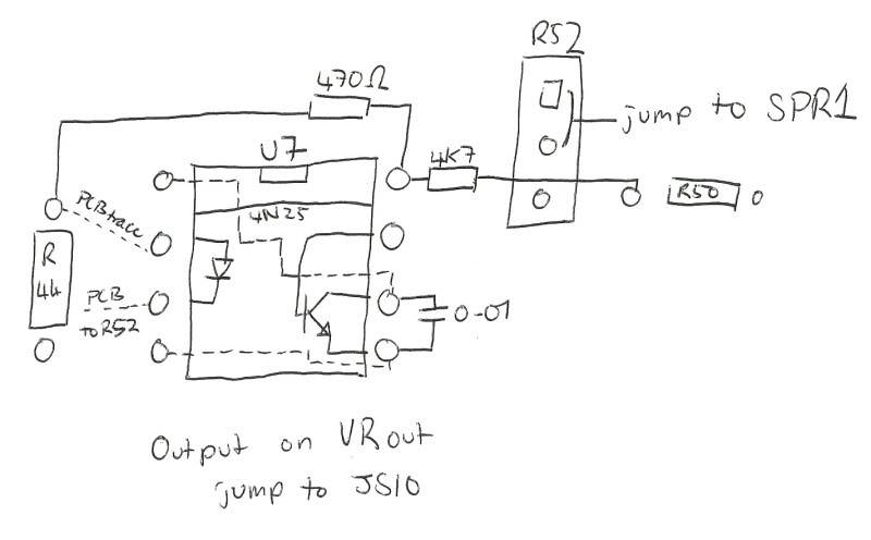
Please excuse the poor quality of the scan, but hopefully it's clear enough.
Nice and neat, and it saves you space in the proto area for other things.
I've been busy and come up with a good way to install the second optoisolater needed for the CKP signal input on a Mk1, using the space that's free from not installing the VR circuit.
Instructions
1) Install the second 4n25 in the lower six pins of U7.
2) Jumper U7 pin 4 to pin 5
3) Jumper U7 pin 1 to pin 6
4) Install a 0.01 capacitor between U7 pin 6 and pin 5 or pin 4
5) Install a 470ohm resistor between the top hole of R44 and U7 pin 8
6) Install a 4k7ohm resistor between the left hole of R50 and U7 pin 8
7) Jumper the top hole of R52 to SPR1
8) Jumper VRout to JS10
Schematic
Please excuse the poor quality of the scan, but hopefully it's clear enough.
Nice and neat, and it saves you space in the proto area for other things.
Last edited by PeteNMA; 04-30-2011 at 03:45 PM.
Reply
 0
0

0


 04-29-2011 | 11:18 AM
#3
Thread Starter
Newb
Joined: Feb 2011
Posts: 39
Total Cats: 0
From: Oxford UK
I know you don't need the second one, but I've had several people tell me that it's worth putting it in as a belt and braces solution.
It's that mess on the proto area that I'm trying to avoid, I figure that the space is there, might as well use it.
It's that mess on the proto area that I'm trying to avoid, I figure that the space is there, might as well use it.
Reply
0
0


Thread
Thread Starter
Forum
Replies
Last Post


