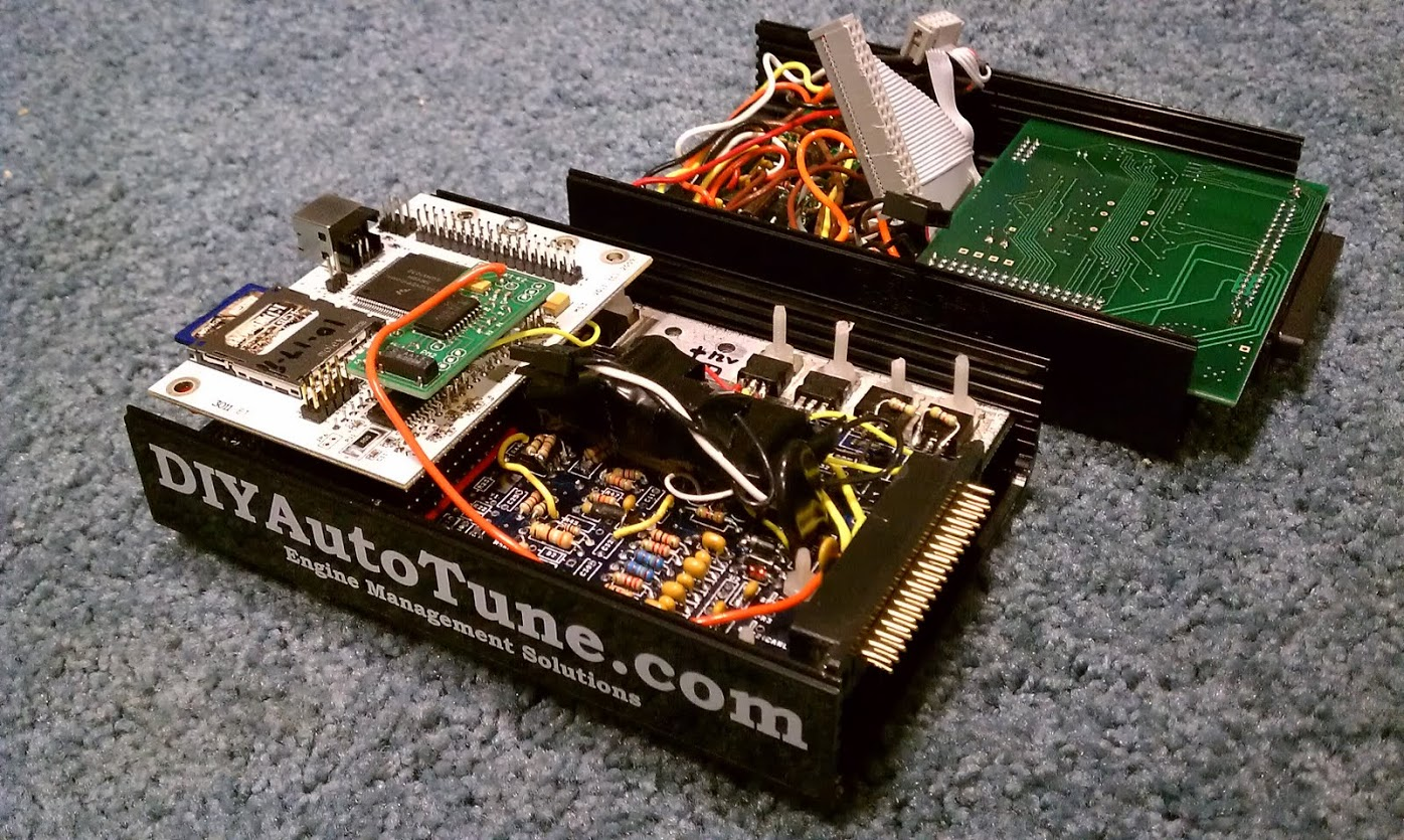
MS3x died, not getting power.
#1
MS3x has no 12v or 5v anywhere on the board. JimStim is providing power, and as soon as I turn the stim on, the power led very flickers dimly. I don't see anything burnt on the boards anywhere...
I'm guessing a short or trace fried, but I can't find it.
I've checked at U5, Q9, Q12, etc, etc.....nothing....where do I look now?
I am/was using Frank's alternator board, but have just unhooked it and that red wire to try and eliminate possible problems.
And yes, I know I did a whole lot more crap than I needed to. Wish I would've paid a little more attention and seen those awesome build pages.
Thanks
#2
To check for a short in the Megasquirt PCB, power up the Megasquirt on a Stimulator or on the car and check the following points for voltage with a multimeter.
You should find the same voltage as the battery voltage on the following points: S12, S12C, the center legs of Q9 and Q12, the left (non-banded) end of D3, the left leg of U5, and the left (banded) end of D9.
You should have 5 volts at the following points: S5, the two +5V holes in the proto area, the right (non-banded) end of D9, the right leg of U5, the left (banded) end of D19, and pins 1, 20, and 31 of the CPU.
Let me know where you find the correct voltages, and where you find the wrong ones.
#6
Update: in Diode Test mode, D19/D9/D17 show .165 in both directions...d12 shows 0 in both directions.
Removed one leg of D19:
12v at s12
1mv at S12c
12v at center legs of Q9/Q12
12v at Left end of D3
1.3mv at left left of U5
1.3mv at left end of D9
"You should have 5 volts at the following points: S5, the two +5V holes in the proto area, the right (non-banded) end of D9, the right leg of U5, the left (banded) end of D19, and pins 1, 20, and 31 of the CPU."
I get .66v everywhere above.
Last edited by KYWalker; 05-19-2017 at 03:27 PM.
#13
Maybe not right at this moment, but trubokitty.com has been very helpful finishing the build....just wish I saw that before I had already built 3/4 of it. I think I just got excited and forgot everything.
It might come in real handy if I have to build another to replace this one doh!
Oh, and what started this mess, was of course my fault...forgot to tighten battery cables. Going down the road after changing the breakin oil and positive cable jumps off...very bright dash....then bad.
It might come in real handy if I have to build another to replace this one doh!
Oh, and what started this mess, was of course my fault...forgot to tighten battery cables. Going down the road after changing the breakin oil and positive cable jumps off...very bright dash....then bad.
#14
check the Engine, and Room fuses.
then check the board for all these components:
http://www.msextra.com/doc/pdf/html/...e-1.4-192.html
then check the board for all these components:
http://www.msextra.com/doc/pdf/html/...e-1.4-192.html
#15
"You should find the same voltage as the battery voltage on the following points: S12, S12C, the center legs of Q9 and Q12, the left (non-banded) end of D3, the left leg of U5, and the left (banded) end of D9."
I reinstalled D19 (D10 is removed) and have 12v at S12, center Q9/Q12, left D3.
I have 1.3mv at S12C, left U5, and left D9.
Notice that D10 is removed...otherwise, I get the short and no voltage anywhere.
Removed D11 & D12, now get:
.8V at S12C, left U5, and left D9.
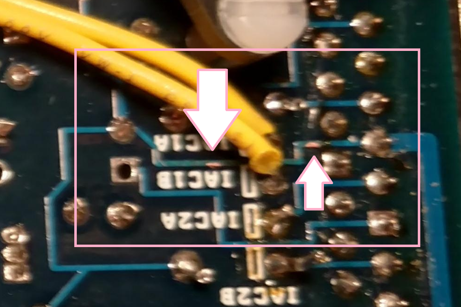
Also found more bared traces...although they seem to be intact....between left D10 and left d12
Last edited by KYWalker; 05-19-2017 at 09:21 PM.


