MS3 w/o MS3x crank and ignition signal issue and MS3x question
#1
Got some questions about the MS3X board(injector and ignition).
On the ms3 original board the injector circuit built like 2*20A IRFIZ34GPBF-ND Hexmosfet, but on the ms3x board has just 8*5A vnd5n mosfet.
2002 Miata 1.8VVT with low impedance injectors(3ohm), using pwm modulation...
According to this wiring wiring diagramm, for the injectors circuit, we use 4 VND5N and 2 for the inition, or how does it work? Will the ms3x board enough to drive 4 lowZ injectors? Also we have to use the VVT, Flexfuel sensor, Boost solenoid, knock module or should I use the original elements for the injector circuit(Q12,Q11,Q5,Q9,Q3,Q1)

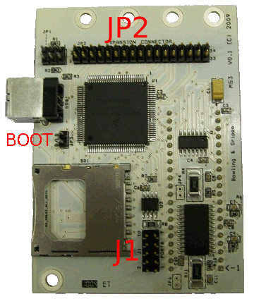
The V3.0 board looks like this, the U5 hasnt install yet:

On the ms3 original board the injector circuit built like 2*20A IRFIZ34GPBF-ND Hexmosfet, but on the ms3x board has just 8*5A vnd5n mosfet.
2002 Miata 1.8VVT with low impedance injectors(3ohm), using pwm modulation...
According to this wiring wiring diagramm, for the injectors circuit, we use 4 VND5N and 2 for the inition, or how does it work? Will the ms3x board enough to drive 4 lowZ injectors? Also we have to use the VVT, Flexfuel sensor, Boost solenoid, knock module or should I use the original elements for the injector circuit(Q12,Q11,Q5,Q9,Q3,Q1)

The V3.0 board looks like this, the U5 hasnt install yet:

Last edited by wolfblind; 01-16-2015 at 05:43 AM.
#4
You can use the mainboard injector drivers to peak and hold low impedance injectors in batch or semi-sequential.
The MS3X board's VNDs do not peak and hold. If you wish to drive low impedance injectos sequentially, I would look for an appropriate peak and hold driver.
If you're looking to build one yourself, you can go with one of these (I would put it in an external enclosure instead of attempting to fit it with the ECU).
Peak&Hold Injector Driver Board for Megasquirt
Or there are other solutions on the market that are ready to go. I've used this one a few times with good success.
Acceleronics VersaFueler info page
#5
Thanks Ben, do it like this...
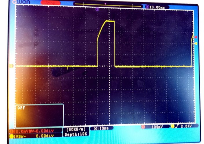
The other issue what I have a basic ms3 without ms3x board, I can get a 4V Spark output signal, what the miata normally has, I reach max 2,8V and the spark isnt strong enough, and the car also wont start.
The circuit wired for VR, I played with the R52 and R56, like on Frank Westfield Mx5 webpage and checked with multimeter and scope the signal and I also got a signal generator. Or should I use the Opto circuit?
Can somebody give a basic msq files to start the car?
I got a 1994 1.8 NA miata using stock coils, I also got now an NBFL coils.... Built after the Franks website 90-97NA MS3...
#6
I'm struggling for 3days now a basic ms3 whitout ms3x board, I can get a 4V Spark output signal, what the miata normally has, I reach max 2,8V and the spark isnt strong enough, and the car also wont start.
Standard miata ignition 10ms/1V ch2:

Now:

The Board(EGT and Launch on proto not wired in)

The test signal generator, do I apply normal 5v square waveform to VR-IN?

I also cant measure any signal on JP2 pin 9 and pin 12 where normally, the ignition come out(doesnt matter if Spark output MS3X or Led) , however on the J1 pin 1-2, can catch an injector signal, when Main Fuel Output: MS3X ON. How can I get the signal for igniton, what should I turn on in Tunerstudio?
The circuit wired for VR, I played with the R52 and R56(what is correct setup for this?), like on Frank Westfield Mx5 webpage and checked with multimeter and scope the signal and I also got a signal generator. Or should I use the Opto circuit?
I got a 1994 1.8 NA miata using stock coils, I also got now an NBFL coils.... Built after the Franks website 90-97NA MS3: 90 ? 97 MS3 | Frank's Westfield MX5 90 ? 97 MS3 |...
Also found this:
----- Hardware Settings -----
MS3 - Crank Pot -> R52: 50,2Kohm (mid value)
MS3 - Crank Pot -> R56: 1,27Kohm (mid value)
MS3 - JP1 Jumper -> conected pins 1 and 2
MS3 - J1 Jumper -> connect pind 3 and 4
MS3 - R57 -> slot empty (no resistor)
MS3X - Cam pot -> R11: 2,4 Kohm (max value)
MS3X - Cam pot -> R32: 93,2Kohm (max value)
MS3X - JP7 Jumper -> connected
Standard miata ignition 10ms/1V ch2:

Now:

The Board(EGT and Launch on proto not wired in)

The test signal generator, do I apply normal 5v square waveform to VR-IN?

I also cant measure any signal on JP2 pin 9 and pin 12 where normally, the ignition come out(doesnt matter if Spark output MS3X or Led) , however on the J1 pin 1-2, can catch an injector signal, when Main Fuel Output: MS3X ON. How can I get the signal for igniton, what should I turn on in Tunerstudio?
The circuit wired for VR, I played with the R52 and R56(what is correct setup for this?), like on Frank Westfield Mx5 webpage and checked with multimeter and scope the signal and I also got a signal generator. Or should I use the Opto circuit?
I got a 1994 1.8 NA miata using stock coils, I also got now an NBFL coils.... Built after the Franks website 90-97NA MS3: 90 ? 97 MS3 | Frank's Westfield MX5 90 ? 97 MS3 |...
Also found this:
----- Hardware Settings -----
MS3 - Crank Pot -> R52: 50,2Kohm (mid value)
MS3 - Crank Pot -> R56: 1,27Kohm (mid value)
MS3 - JP1 Jumper -> conected pins 1 and 2
MS3 - J1 Jumper -> connect pind 3 and 4
MS3 - R57 -> slot empty (no resistor)
MS3X - Cam pot -> R11: 2,4 Kohm (max value)
MS3X - Cam pot -> R32: 93,2Kohm (max value)
MS3X - JP7 Jumper -> connected
#8
Built like here: https://www.diyautotune.com/tech_art...azda_miata.htm
Through d14 and d16 led, and 330k resistor, do I need some another modifications in MS3, using stock miata coils?
Friend of mine has Ms3 with MS3X, he has no signal on JP2, only on J1, in tunerstudio MS3x is on, should we switch on something else, jumper or something to make it work?

We built both after FrankWestfiled guide, but none of them work perfect ...
...
Through d14 and d16 led, and 330k resistor, do I need some another modifications in MS3, using stock miata coils?
Friend of mine has Ms3 with MS3X, he has no signal on JP2, only on J1, in tunerstudio MS3x is on, should we switch on something else, jumper or something to make it work?

We built both after FrankWestfiled guide, but none of them work perfect
 ...
...
#10
 ...I use ALED and WLED for Spark output.
My friend has the other ms3 with expander, and I have w/o ms3x just a basic ms3.
What I've experinced today, is strange for me: I start from 5Hz till up to 110Hz with signal generator to simulate the rpm range,(full ignition and spark plugs connected to a battery) I get sparks just from one side and go higher like 30Hz then I get sparks just from the other 2 spark plug, then up to 100Hz and again I get sparks from the other side[sometimes I get very tiny sparks from the other ignitor], so the 4 plugs dont spark nearly togehther, like normally do....
What resistance(R52,R56) should I use for the VR?
I also got now '90 Miata Ignition module and BIP373 to build circuit, so after the LED circuit should I use 20-30 ohm before BIP373 connected?
My friend 2004 Miata with MS3X:
No ignition or any signal on JP2, just on J1, same as mine, I dont understand....

#11
Do I need Cam input for MS3, or just normal CAS signal is enough for MS3?
Hmm:
http://www.msextra.com/doc/ms3/4g63.html
White = 'cam' (2 slots) - connects to pin 32 on MS3X connector , I dont have the Ms3x, so js10?
Hmm:
http://www.msextra.com/doc/ms3/4g63.html
White = 'cam' (2 slots) - connects to pin 32 on MS3X connector , I dont have the Ms3x, so js10?
Thread
Thread Starter
Forum
Replies
Last Post
Zaphod
MEGAsquirt
47
10-27-2018 12:00 AM
Frank_and_Beans
Supercharger Discussion
13
09-12-2016 09:17 PM


