MS3 PnP build
#1
In a similar way as I did the MS2 PnP build, I'm in the process of building a MS3 PnP. Instructions here.
Not quite finished yet, parts for the alternator circuit are on backorder :(.
Remarks or additions welcome.

Not quite finished yet, parts for the alternator circuit are on backorder :(.
Remarks or additions welcome.
#4
Define big. I'm really not a fan of the monstrous wiring loom with 2 DB37's and the (unprotected) 64 pin connector.
It fits very well actually. MS3X fits as normal with wiring between the 2 pcb's.
You could stack an extra socket to clear the connector, but that would mean modifying the left endplate. I found it easier to cut a piece of the cpu. With enough backlight, you can clearly see that there's nothing there.
The yellow connector can be bolted to the heatsink through the existing mounting holes of Q12 and Q16. No need to drill a single hole.
Last edited by WestfieldMX5; 10-28-2011 at 07:24 AM. Reason: Added connector info
#10
Do my pictures show? Ever since the forum blocked my country, posting has been a pain :(. I only see the first picture, the others every now and then.
Editing a post usually sends me to a broken link .
.
Anyway, maybe by stacking an extra socket would work, it would be thight though. You'd only have to enlarge the holes for the SD and USB. Might be worth looking into by those who are afraid of cutting the daughterboard.
Editing a post usually sends me to a broken link
 .
.Anyway, maybe by stacking an extra socket would work, it would be thight though. You'd only have to enlarge the holes for the SD and USB. Might be worth looking into by those who are afraid of cutting the daughterboard.
#11
Joined: Jun 2005
Posts: 19,338
Total Cats: 574
From: Fake Virginia
pictures show fine.
pretty awesome solution.
did you make a new endplate for the db37 side or just leave open holes? because if you made a new one... you can make a second new one.
or with help.
http://www.lmbheeger.com/products.asp?catid=68
pretty awesome solution.
did you make a new endplate for the db37 side or just leave open holes? because if you made a new one... you can make a second new one.
or with help.
http://www.lmbheeger.com/products.asp?catid=68
#15
Joined: Jun 2005
Posts: 19,338
Total Cats: 574
From: Fake Virginia
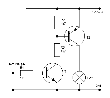
this week I'll be testing the ms3-controlled alternator circuit. it's pretty simple. based on this image:

Use a TIP120 + TIP125 and the three resistors. hook it to a spare output (I pick FIDLE) and set it thusly:
*checkmark* Enabled
Power on value 0
Trigger value 1
condition 1: battery voltage < 14.0 (hysteresis 0.1 or whatever)
AND
condition 2: rpm > 600 (hysteresis 30ish)
presumably it's fast enough to handle alternator control.. I guess I'll see.
on the bench, it certainly seems to work as it should. is there a voltage limit on the alternator input or does it matter?
Thoughts?
#20
Joined: Jun 2005
Posts: 19,338
Total Cats: 574
From: Fake Virginia
yeah, it makes batt voltage oscillate and that makes everything else oscillate so in short DO NOT USE IT.
however if you want to do something creative, you can hook the output of the known working alternator circuit that goes to the field coil to the place in the above where it says +12 and the output of the above to the field coil and then set the output to only be enabled for over 450 rpm so it doesn't charge during cranking and make your belt squeal for 20 seconds every time you start your car.
however if you want to do something creative, you can hook the output of the known working alternator circuit that goes to the field coil to the place in the above where it says +12 and the output of the above to the field coil and then set the output to only be enabled for over 450 rpm so it doesn't charge during cranking and make your belt squeal for 20 seconds every time you start your car.


 .
.


