
MS3/3x users: How to use all your spare I/O
 05-25-2016, 04:48 PM
#1
SADFab Destructive Testing Engineer


Thread Starter
iTrader: (5)
Join Date: Apr 2014
Location: Beaverton, USA
Posts: 18,642
Total Cats: 1,866
Although the MS3x handles a lot of I/O, sometimes you want more. Hes is a general guide on what you can use, and how. It is by no means a complete guide. Refer to the manuels for that.
To start out I will go over the 2 types of input (Analog, Digital) and the necessary circuits to implement different types of I/O for each one. Then I will give an example of how I did it.
Before I start read this important warning. DO NOT HOOK AN EXTERNAL SIGNAL DIRECTLY TO A PROCESSOR PIN. All analog and digital inputs should have a protective circuit between the external circuit and the processor. This is a good way to fry your board.
Analog:
Analog inputs convert a 0-5v input signal into a digital value. Common uses are temperature sensors, linear pressure sensors, The 2 most common usages are a 0-5v linear pressure sensor, or a GM temperature circuit.
Analog inputs:
MS3x (These are available directly on the ms3x db37):
Second EGO
Ext Map
Spare ADC
These 3 inputs are ready to accept a 0-5v input. For use with a GM temperature sensor they will need a 2.49k pullup resistor (Which may be on the ms3x, and might just need a jumper, can't tell from the schematics)
MS3 (These all need circuits built and are not connected externally):
JS4
JS5
Both these need circuits built to handle a 0-5v input. Here is an excerpt from the manuel.
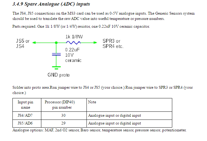
In this image you can see the processor pin numbers. You can jumper to the pins on the bottom of the board, or looks for labeled pads on the bottom of the board.
To use a GM sensor with these 2 inputs then build the same circuit that is built on the mainboard:
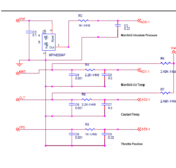
So there is 5 analog inputs you can use for different sensors. You can also use them for blending boost (think a potentiometer to adjust the voltage). They can also be used to control launch control rpm.
Digital:
Digital inputs take in a signal and read it as either a 0 or a 1. If you ground a digital input its a 0. If you give it 5v (or let it float) its a 1. The MS3 has a ton of digital inputs, and they can do all sorts of stuff.
MS3x digital inputs (Externally available on the DB37):
Flex In
PT4
Datalog
Tableswitch
These 4 inputs are ready to accept your signal. For example, I have a VR conditioner board that outputs a 0-5v signal for VSS. That inputs goes directly into one of the digital inputs and can be used for a speed reading.
Also see here for how to use the VSS that may already be on your cluster (https://www.miataturbo.net/megasquir...6-miata-82518/)
There are 3 other inputs that are accessible to do what you please with. But keep in mind these need protective circuits for outside signals.
S10 (PT5)
JS7 (PE0)
JS11 (Keep in mind this is used for the knock module, so if you plan on using a knock module do not use this)
PE1
Here is an excerpt from the manual on the protective circuits for a ground switched input and a 12v switched input
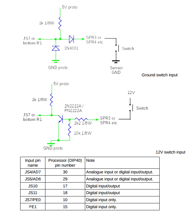
In this image you can see the processor pin numbers. You can jumper to the pins on the bottom of the board, or looks for labeled pads on the bottom of the board.
As you can see there is a decent amount of I/O that you can get even without an external CAN I/O box. That being said I am in the process of getting my tinyIOx reading even more sensors and will have another writeup for that when the time comes. Let me know if you have any questions, or corrections.
Manuals for reference:
http://www.msextra.com/doc/pdf/MS3ba...rdware-1.4.pdf
http://www.msextra.com/doc/pdf/MS3XV30_Hardware-1.4.pdf
My wiring spreadsheet:
https://docs.google.com/spreadsheets...it?usp=sharing
To start out I will go over the 2 types of input (Analog, Digital) and the necessary circuits to implement different types of I/O for each one. Then I will give an example of how I did it.
Before I start read this important warning. DO NOT HOOK AN EXTERNAL SIGNAL DIRECTLY TO A PROCESSOR PIN. All analog and digital inputs should have a protective circuit between the external circuit and the processor. This is a good way to fry your board.
Analog:
Analog inputs convert a 0-5v input signal into a digital value. Common uses are temperature sensors, linear pressure sensors, The 2 most common usages are a 0-5v linear pressure sensor, or a GM temperature circuit.
Analog inputs:
MS3x (These are available directly on the ms3x db37):
Second EGO
Ext Map
Spare ADC
These 3 inputs are ready to accept a 0-5v input. For use with a GM temperature sensor they will need a 2.49k pullup resistor (Which may be on the ms3x, and might just need a jumper, can't tell from the schematics)
MS3 (These all need circuits built and are not connected externally):
JS4
JS5
Both these need circuits built to handle a 0-5v input. Here is an excerpt from the manuel.
In this image you can see the processor pin numbers. You can jumper to the pins on the bottom of the board, or looks for labeled pads on the bottom of the board.
To use a GM sensor with these 2 inputs then build the same circuit that is built on the mainboard:
So there is 5 analog inputs you can use for different sensors. You can also use them for blending boost (think a potentiometer to adjust the voltage). They can also be used to control launch control rpm.
Digital:
Digital inputs take in a signal and read it as either a 0 or a 1. If you ground a digital input its a 0. If you give it 5v (or let it float) its a 1. The MS3 has a ton of digital inputs, and they can do all sorts of stuff.
MS3x digital inputs (Externally available on the DB37):
Flex In
PT4
Datalog
Tableswitch
These 4 inputs are ready to accept your signal. For example, I have a VR conditioner board that outputs a 0-5v signal for VSS. That inputs goes directly into one of the digital inputs and can be used for a speed reading.
Also see here for how to use the VSS that may already be on your cluster (https://www.miataturbo.net/megasquir...6-miata-82518/)
There are 3 other inputs that are accessible to do what you please with. But keep in mind these need protective circuits for outside signals.
S10 (PT5)
JS7 (PE0)
JS11 (Keep in mind this is used for the knock module, so if you plan on using a knock module do not use this)
PE1
Here is an excerpt from the manual on the protective circuits for a ground switched input and a 12v switched input
In this image you can see the processor pin numbers. You can jumper to the pins on the bottom of the board, or looks for labeled pads on the bottom of the board.
As you can see there is a decent amount of I/O that you can get even without an external CAN I/O box. That being said I am in the process of getting my tinyIOx reading even more sensors and will have another writeup for that when the time comes. Let me know if you have any questions, or corrections.
Manuals for reference:
http://www.msextra.com/doc/pdf/MS3ba...rdware-1.4.pdf
http://www.msextra.com/doc/pdf/MS3XV30_Hardware-1.4.pdf
My wiring spreadsheet:
https://docs.google.com/spreadsheets...it?usp=sharing

Reply
 5
5

5
05-25-2016, 06:31 PM
#2
 to you. Thanks for compiling this info.
This link has some good info on automotive sensor:
https://www.autosportlabs.net/RaceCapturePro_Sensors
PS: I'm waiting for you to be the guinea pig for the tinyiox board MS3 integration with a thorough DIY writeup

Reply
0
0
05-25-2016, 07:18 PM
#4
SADFab Destructive Testing Engineer
Thread Starter
iTrader: (5)
Join Date: Apr 2014
Location: Beaverton, USA
Posts: 18,642
Total Cats: 1,866
to you. Thanks for compiling this info.This link has some good info on automotive sensor:
https://www.autosportlabs.net/RaceCapturePro_Sensors
PS: I'm waiting for you to be the guinea pig for the tinyiox board MS3 integration with a thorough DIY writeup
Reply
0
0


