
MS2 V3.0 in MP62 99 Miata
 05-01-2015 | 01:06 PM
#1

Thread Starter
Newb
Joined: Feb 2012
Posts: 19
Total Cats: 0
From: Qu�bec, Canada
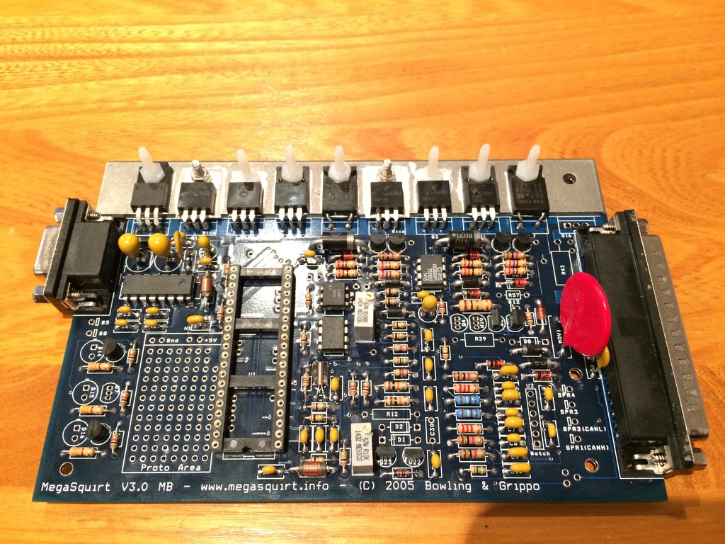
I've been wanting to do the MS2 for sometime now and finally pulled the plug. The easy part of the msextra manual is done. The board is now looking like this:
Now the fun part. As I understand, for a 99 build, the ms2 need to be setup to control:
Alternator
VCIS
Fans
Cam and crank inputs.
Since everybody has now switched to MS3, a lot of the MS2 thread picture links are getting broken and it is quite difficult to extract the good info out of it.
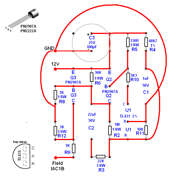
For now, the most relevant alternator circuit i found is this:
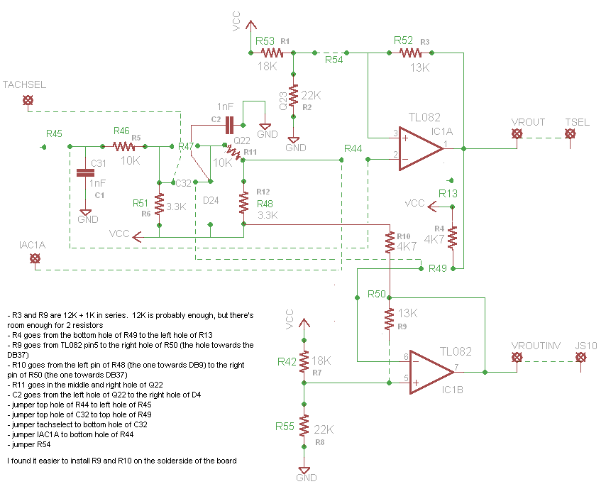
And the best Cam and crank input circuit is this:
I was going to use middle led to control the fan relay as described here:
Megasquirt 2 Mod Kits - Miata Turbo FAQ
And the MK-RelayCtrl I bought for the VCIS.
Next thing wil be to configure the board for PWM IAC with the MK-PWMIAC kit.
Is that about right? Are there better/simpler circuits tu use? Does somebody have a picture of the final thing assembled for reference to manage Proto space?
Thank you
David
Now the fun part. As I understand, for a 99 build, the ms2 need to be setup to control:
Alternator
VCIS
Fans
Cam and crank inputs.
Since everybody has now switched to MS3, a lot of the MS2 thread picture links are getting broken and it is quite difficult to extract the good info out of it.
For now, the most relevant alternator circuit i found is this:
And the best Cam and crank input circuit is this:
I was going to use middle led to control the fan relay as described here:
Megasquirt 2 Mod Kits - Miata Turbo FAQ
And the MK-RelayCtrl I bought for the VCIS.
Next thing wil be to configure the board for PWM IAC with the MK-PWMIAC kit.
Is that about right? Are there better/simpler circuits tu use? Does somebody have a picture of the final thing assembled for reference to manage Proto space?
Thank you
David
Reply
 0
0

0

 05-05-2015 | 04:00 PM
#3
Thread Starter
Newb
Joined: Feb 2012
Posts: 19
Total Cats: 0
From: Qu�bec, Canada
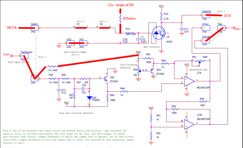
Let's say I keep the MS2. Whitch would be the right way to use the opto circtuit for the cam sensor?
5.2.14.2 hall sensor / optical sensor
5.2.14.3 hall or logic sensor
5.2.14.4 ground switching
5.2.14.2 hall sensor / optical sensor
5.2.14.3 hall or logic sensor
5.2.14.4 ground switching
Reply
0
0
05-05-2015 | 09:13 PM
#4

Newb
Joined: May 2015
Posts: 12
Total Cats: 0
goto this link it has a simple circuit Megasquirt Ii Opto Input Circuit - Forced Induction & N/A Power Mods - MX5Nutz Forum
Reply
0
0
05-06-2015 | 07:58 AM
#6
That link was if you were using the opto for crank and then built a second opto for cam. I don't like building extra circuits if possible.
see post 28-30 here: https://www.miataturbo.net/megasquir...t-83247/page2/
see post 28-30 here: https://www.miataturbo.net/megasquir...t-83247/page2/
Reply
0
0

Thread
Thread Starter
Forum
Replies
Last Post
Frank_and_Beans
Supercharger Discussion
13
09-12-2016 09:17 PM


