
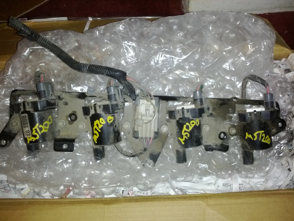
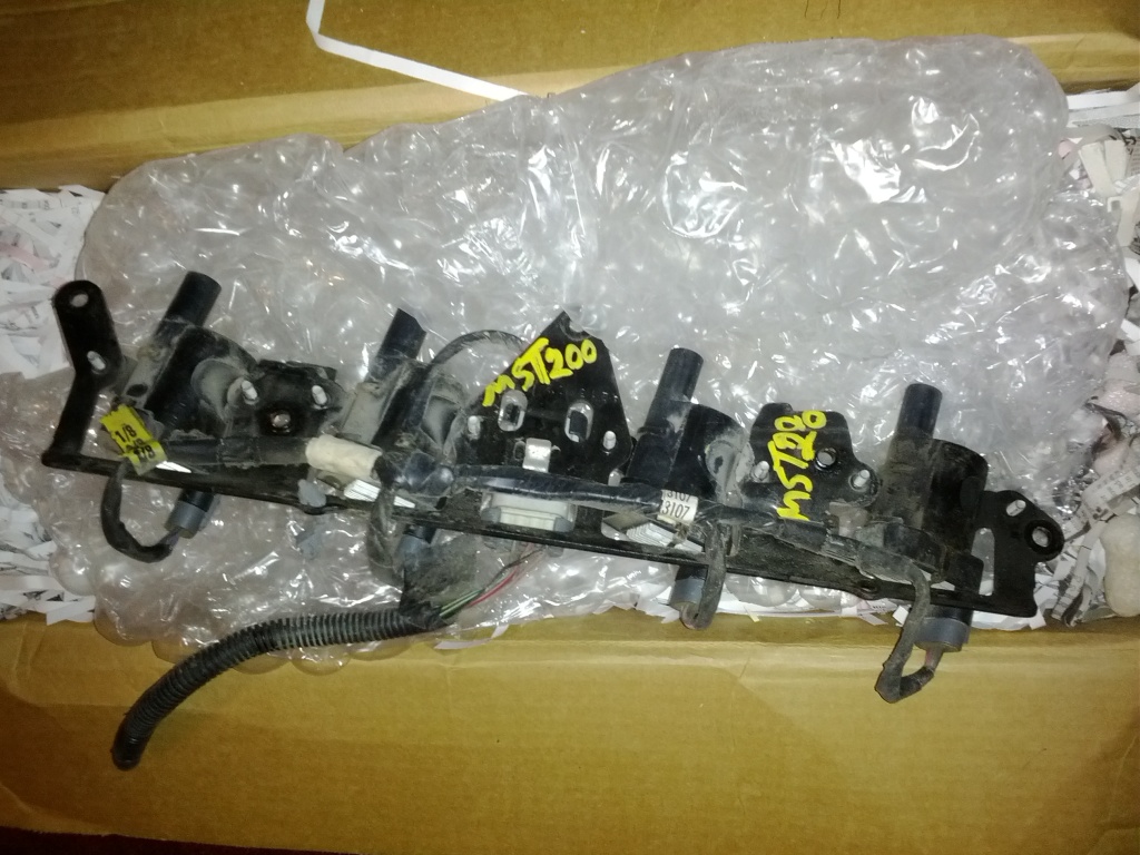
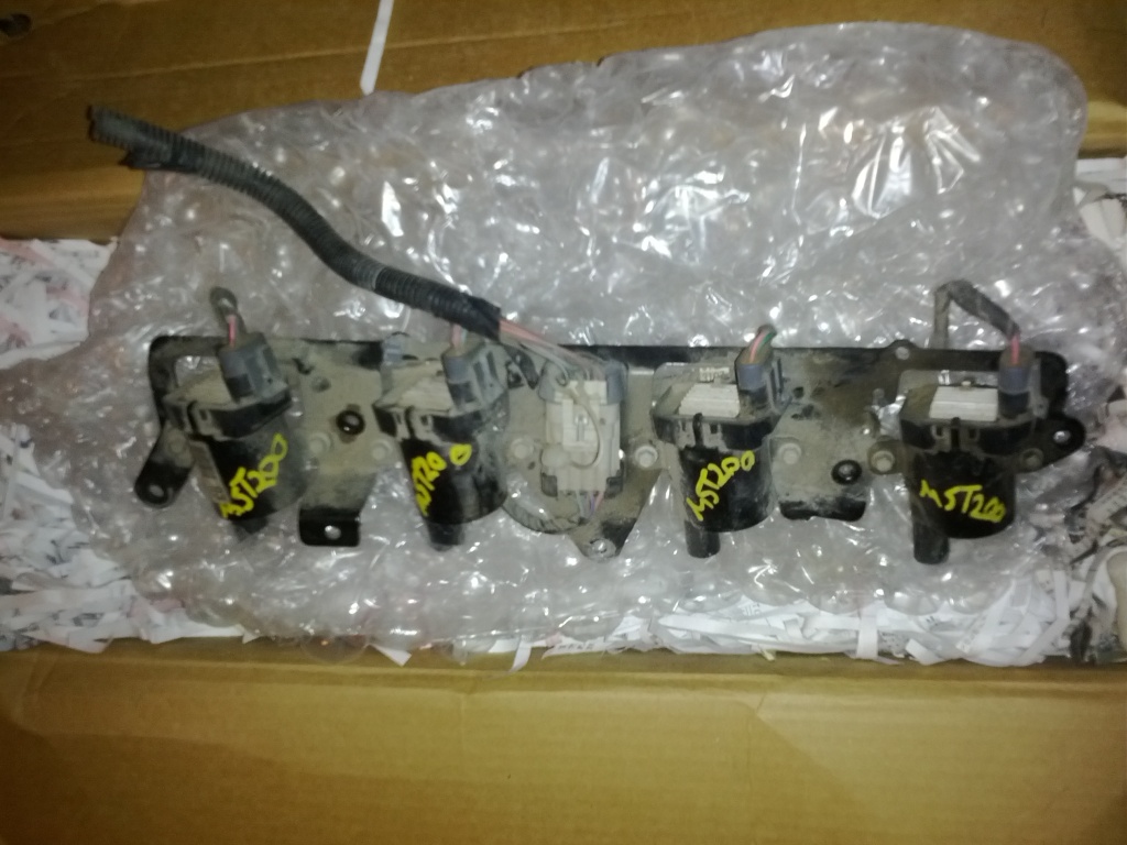
MS2 and LS2 coils
 04-05-2012 | 02:52 PM
#1

Thread Starter
Junior Member
iTrader: (1)
Joined: Dec 2006
Posts: 323
Total Cats: 2
From: San Francisco, CA
I'm planning on upgrading to LS2 truck coils.
What kind of changes do I need to make on the MS2?
It's the DIYPNP from Braineack.
I know to set the dwell to 5-5.5.
But since I have and 94 and the LS2 coils don't have a tach output, how do I wire my tach to work?
Are there suppose to be 4 signal wires coming off the MS2 to fire off each coil individually? Reading about the wiring being the same as COP seems like it will make the all the coils fire all the time and not sequential. Of course, I'm probably wrong.
Thanks
Reply
 0
0

0

 04-05-2012 | 06:14 PM
#5
Thread Starter
Junior Member
iTrader: (1)
Joined: Dec 2006
Posts: 323
Total Cats: 2
From: San Francisco, CA
However, I've never taken my ms2 apart before so I don't really understand the modifying part. I bought my ms2 from you so I don't really know what's in it. Has this already been set up or can I send this to you to get done?
Thanks
Reply
0
0
04-06-2012 | 05:10 PM
#7
Thread Starter
Junior Member
iTrader: (1)
Joined: Dec 2006
Posts: 323
Total Cats: 2
From: San Francisco, CA
To go batch, do I just ground all the grounds to the head, 12v to the blue wire, and 2 coils to brown and 2 coil to brown/yellow? Won't that fire off 2 coils at a time?
What should I do about the tach reading? Can I tap the black/white wire to a wire near the ECU to get a tach reading?
Looks like wiring up for batch is a whole lot easier than sequential. Is there a major advantage to go sequential? I've read smoother idle, but wouldn't I get that from the stronger spark anyway?
Reply
0
0
04-06-2012 | 05:45 PM
#8

 Its how the stock ECU does these things.
Yes, batch is super easy to wire. Someone more experienced can chime in on the benifits of sequential on an MS2/DIYPNP. I experienced smoother idle when I went from my failboat 99/00 coil to COPs, but YMMV
Reply
0
0
04-06-2012 | 09:50 PM
#9
Thread Starter
Junior Member
iTrader: (1)
Joined: Dec 2006
Posts: 323
Total Cats: 2
From: San Francisco, CA
Ah, now it's starting to make sense. Sorry used to working on american cars with distributers.
I have a 94 so the tach reading comes from the coil unlike the 99.
Unfortunately, the LS coils don't have a tach signal.
I have a 94 so the tach reading comes from the coil unlike the 99.
Unfortunately, the LS coils don't have a tach signal.
Reply
0
0
04-12-2012 | 08:20 PM
#12

Junior Member
Joined: Mar 2011
Posts: 163
Total Cats: 0
From: Guildford, UK
Have a look at 2I on your OEM connector.
http://www.boostedmiata.com/gallery2...ne_harness.jpg
Or it could be 2I shielded grey from pin 26 on DB37.
http://www.boostedmiata.com/gallery2...ne_harness.jpg
Or it could be 2I shielded grey from pin 26 on DB37.
Reply
0
0
 04-13-2012 | 03:01 AM
#14
Thread Starter
Junior Member
iTrader: (1)
Joined: Dec 2006
Posts: 323
Total Cats: 2
From: San Francisco, CA
Have a look at 2I on your OEM connector.
http://www.boostedmiata.com/gallery2...ne_harness.jpg
Or it could be 2I shielded grey from pin 26 on DB37.
http://www.boostedmiata.com/gallery2...ne_harness.jpg
Or it could be 2I shielded grey from pin 26 on DB37.
But does this mean if I have the tach circuit built in, the tach is already getting the signal from the ms2 and I dont have to run any additional wires?
Reply
0
0
 04-14-2012 | 10:56 AM
#17
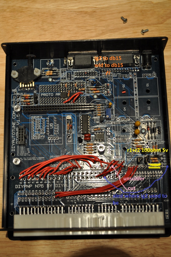
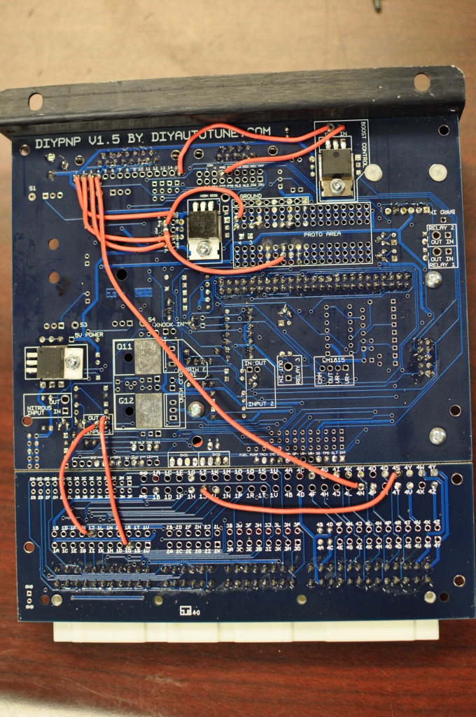
just desolder the red wire to ign2/1H. then just move the wire on ald from 1L to 1H. then do the resistors and jumpers to the db15.
you'll have to move the cooling fan off aled. So jump pao to relay 1 IN, then relay 1 OUT to 1L. youll need to copy the output settings in TS for ALED to the Pa0 output.
you'll have to move the cooling fan off aled. So jump pao to relay 1 IN, then relay 1 OUT to 1L. youll need to copy the output settings in TS for ALED to the Pa0 output.
Reply
0
0
04-14-2012 | 06:49 PM
#18
Thread Starter
Junior Member
iTrader: (1)
Joined: Dec 2006
Posts: 323
Total Cats: 2
From: San Francisco, CA
My PA0 is currently going to boost control in. Boost control out is going to db15 - pin 15.
What should I do?
Thanks
What should I do?
Thanks
Last edited by Halcyon; 04-14-2012 at 08:45 PM.
Reply
0
0
 04-14-2012 | 09:35 PM
#20
Thread Starter
Junior Member
iTrader: (1)
Joined: Dec 2006
Posts: 323
Total Cats: 2
From: San Francisco, CA
So PT6 to to relay 1 IN, then relay 1 OUT to 1L?
Couple of wire moves.
Couple of resistors.
Couple of jumpers.
Sounds doable.
Where should I look to copy the output settings in TS for ALED to the PT6 output?
Thanks
Couple of wire moves.
Couple of resistors.
Couple of jumpers.
Sounds doable.
Where should I look to copy the output settings in TS for ALED to the PT6 output?
Thanks
Reply
0
0


