MS1/MSPNP Closed-Loop EBC -- Works Well on my Car -- Details
#1
Thread Starter
Elite Member
iTrader: (4)
Joined: Mar 2008
Posts: 6,301
Total Cats: 696
From: Granbury, TX
Step 1: Wastegate Only:
I've taken a building block approach to EBC with my MSPNP. For the first couple of months after turbo install, I just concentrated on tuning my basic performance on the wastegate. This was facilitated by an "EBC Enable/Disable" toggle switch that I hid in my engine compartment (since my youngest daughter starts driving in October and has her eyes set squarely on the Miata). This is what my basic Greddy wastegate control looks like on a 3rd gear pull:
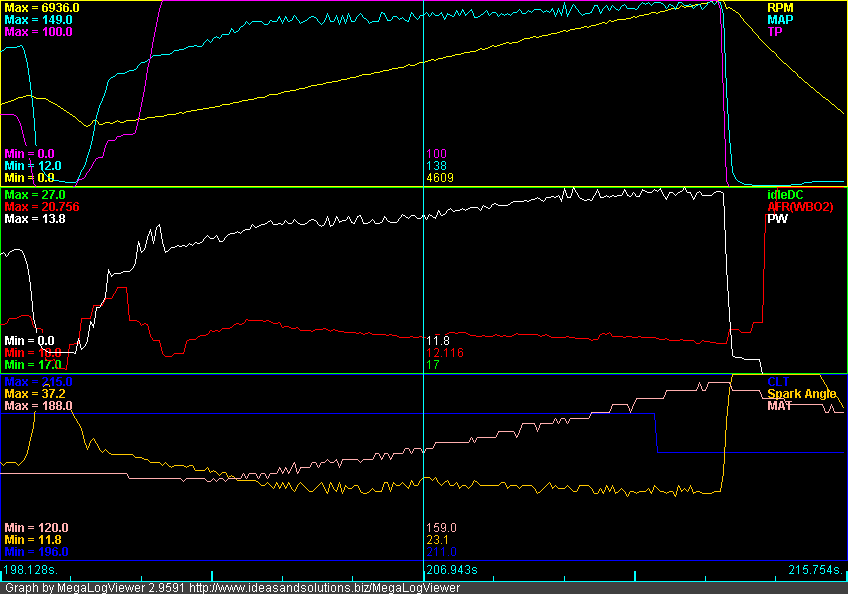
Overall, the control isn't bad. The wastegate kicks in at around 3300RPM and 5.2psi of boost. From 3300RPM to 6900RPM, there is a gradual 2.5psi of boost creep. Two things contribute to boost creep on my car:
1. I don't run an intercooler, therefore there is no pressure loss as the intake flow increases with RPM.
2. I run a performance cat and a 2.5" exhaust which gives less back pressure than stock. I use the stock Greddy downpipe with some porting. This tends to skew more of the exhaust flow through the turbine instead of the wastegate as flow increases.
Before delving into any form of boost control, you need to ensure that your wastegate basically works so that your boost control has a chance of controlling things. Also, your target boost needs to be higher than the maximum boost generated by the wastegate. The curve here is easily controllable and my boost target of 10psi is comfortably above 7.7psi. So, on to the next step.
Step 2: Open Loop EBC:
My next step was open loop EBC. I followed the directions in the MSPNP manual for this. Basically, you:
1. Setup the valve parameters;
2. Disable closed loop control; and
3. Tune valve duty cycle targets.
For valve parameters, I bought the DIY EBC valve and just used the defaults. Didn't mess with it. Seems to work.
There are a couple of ways to disable the closed loop control. The MSPNP manual recommends setting all cells of your "Boost kPa Target" table to 70kPa and the "Closed Loop kPa Limit" to 20kPa. Thus, so long as your MAP is at 90kPa or above (as it will be in boost), you will be beyond the "Closed Loop kPa Limits" and operating on open-loop duty cycles.
The other way to disable closed loop control is simply to set 0 as the "Closed Loop kPa Limit." Due to the normal noise on the MAP signal, this condition will never be true except for rare, momentary transitions.
Tuning the valve duty cycles is straightforward. What I did was log a series of third gear pulls with my entire duty cycle table set to a contant value. I would do the third gear pull until I either hit my RPM limit or my boost limit. This was my sequence:
1. Set duty cycle table to 100%. This essentially keeps the EBC valve and wastegate closed.
2. Perform a third gear pull. On this first run, you need to be careful because you are going to hit your boost limit WAY before your RPM limit. This run establishes the lowest RPM at which you can hit your target boost.
3. Set duty cycle to 90%.
4. Perform a third gear pull.
5. Repeat the above while incrementally lowering the duty cycle until you are hitting your RPM limit without hitting your boost limit.
With logs in hand, analyze to determine your DC vs. RPM curve for your target boost. My values were:
100%DC -- 3900RPM
90%DC -- 3950RPM
80%DC -- 4000RPM
70%DC -- 4100RPM
60%DC -- 4350RPM
55%DC -- 4400RPM + Held 10psi to Redline
50%DC -- Hit 9psi at 3900RPM and held 9psi to Redline
Armed with the above information, and with the benefit of a few 3rd gear pulls to smooth overshoots and undershoots, I ended up with the following duty cycle target table:
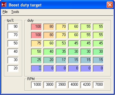
Note that since I have a TPS, I reduced the duty cycles at lower throttle positions to produce more linear throttle response and relieve turbine load at part throttle. This part is strictly optional.
Here's what an open-loop third gear pull looks like:
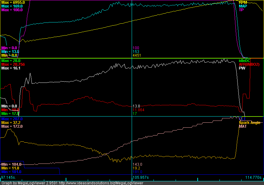
Control is good. You can see the rapid boost ramp from keeping high duty cycles at low RPMs. There is a slight overshoot where EBC starts really controlling around 3900RPM. These is also a slight sag in the middle and a little boost creep at the end. This pull shows boost controlled between 8.5-10psi (average around 9psi). With some more tuning, I'm sure I could get that line straighter.
This pull also illustrates the deficiency in open-loop EBC. The day I tuned it, my average was 10psi. On the day that I logged this pull, it generated 9psi. Open-loop EBC cannot target a boost level. It just sets up physical operating parameters for the valve based upon RPM and TPS. The boost you get depends entirely upon external conditions (atmospheric pressure and temperature, engine compartment heat soak, etc.). This is kind of annoying.
Step 3: Closed-Loop EBC:
So, I lived with Open-Loop EBC for awhile. It was pretty good, and I just tolerated that it would control to "around" 10psi. The word around MT.net was that Closed-Loop EBC didn't work on the MS1. If you wanted closed-loop, you needed at least an MS2. The MSPNP directions were equally discouraging, descibing closed-loop as "experimental" and "use at your own risk."
Well, my friends, the above is total bullshit. Closed-loop EBC works just fine on the MS1. Read on.
One evening, I was driving home from work, and open-loop was only hitting around 8psi. There had been some recent, dramatic weather changes in our area (we were FINALLY below 100°F -- actually, well below), and this was impacting where open-loop was settling. I was near my 3rd gear pull test area, and I had my laptop with me . . . what the heck, let's give it a try.
I setup my target boost table, and left the default values for Proportional Gain (49.8%), Differential Gain (9.8%) and Closed Loop kPa Limit (20kPa). Did a 3rd gear pull. It wasn't pretty (±3psi), but it was obviously controlling. Time to tune.
The MS1 code provides for both proportional and differential gain. Tuning proportional control loops is simple, and you can always achieve a safe and stable gain (I've attached a handy and relatively understandable reference to this post on different control loop types). Differential is a lot trickier, and depends upon a very clean relationship between the control variable and the control parameter to be useful. Our MAP signal is just plain too noisy for it to be of any use, so I ignored it. After setting Differential Gain to 0%, I did 4 3rd gear pulls and quickly settled on a Proportional Gain of 15% and a Closed Loop kPa Limit of 15kPa. I also made sure that my kPa target table had easily attainable targets around the 4000RPM corner to minimize control overshoots. This is where I ended up with my closed loop parameters:
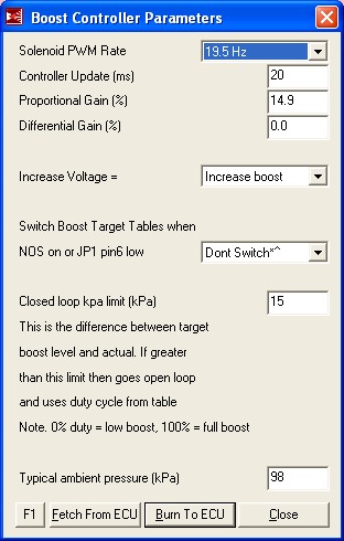
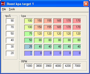
And here's a 3rd gear pull:
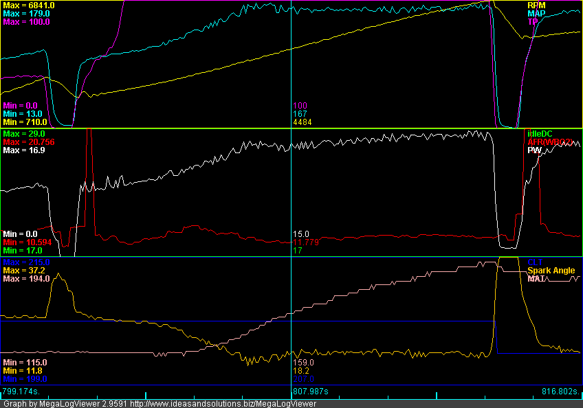
Works well! Still a slight overshoot at the corner, but beyond we're at 10psi ±0.5psi. And, theoretically, this control method should not be dependent upon weather conditions (although I've only been running it this week -- we'll see how it handles more drastic weather changes).
Comparisons:
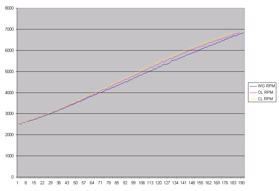
Here's a comparison of the three control methods in RPM vs. Time. Note that time is in MS logging frequency units (~16Hz -- a value of 160 is about 10 seconds). The lines are 2500RPM to 6900RPM pulls. The steeper the line, the faster the acceleration. More boost = more power . . . no suprise here.
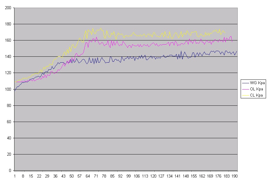
Here's another comparison of kPa vs. Time for the same three pulls. Pretty happy with the closed-loop line.
Conclusions:
1. Closed-loop EBC on MS1 works just fine. Use it.
2. Make sure you do things in sequence. Step 1 is to make sure your wastegate can adequately control boost.
3. Step 2 is to tune open loop. This is important. Not only is open-loop the fallback control method if closed-loop doesn't work, but it also provides the basic duty cycle value that the closed-loop algorithm modifies to achieve desired boost. If it is way off, you don't have a chance.
4. Step 3 is to tune closed loop. Apply KISS. Do proportional only and take it easy with the gains and targets so you get good control.
I'm cross-posting this to my build thread as well.
I've taken a building block approach to EBC with my MSPNP. For the first couple of months after turbo install, I just concentrated on tuning my basic performance on the wastegate. This was facilitated by an "EBC Enable/Disable" toggle switch that I hid in my engine compartment (since my youngest daughter starts driving in October and has her eyes set squarely on the Miata). This is what my basic Greddy wastegate control looks like on a 3rd gear pull:

Overall, the control isn't bad. The wastegate kicks in at around 3300RPM and 5.2psi of boost. From 3300RPM to 6900RPM, there is a gradual 2.5psi of boost creep. Two things contribute to boost creep on my car:
1. I don't run an intercooler, therefore there is no pressure loss as the intake flow increases with RPM.
2. I run a performance cat and a 2.5" exhaust which gives less back pressure than stock. I use the stock Greddy downpipe with some porting. This tends to skew more of the exhaust flow through the turbine instead of the wastegate as flow increases.
Before delving into any form of boost control, you need to ensure that your wastegate basically works so that your boost control has a chance of controlling things. Also, your target boost needs to be higher than the maximum boost generated by the wastegate. The curve here is easily controllable and my boost target of 10psi is comfortably above 7.7psi. So, on to the next step.
Step 2: Open Loop EBC:
My next step was open loop EBC. I followed the directions in the MSPNP manual for this. Basically, you:
1. Setup the valve parameters;
2. Disable closed loop control; and
3. Tune valve duty cycle targets.
For valve parameters, I bought the DIY EBC valve and just used the defaults. Didn't mess with it. Seems to work.
There are a couple of ways to disable the closed loop control. The MSPNP manual recommends setting all cells of your "Boost kPa Target" table to 70kPa and the "Closed Loop kPa Limit" to 20kPa. Thus, so long as your MAP is at 90kPa or above (as it will be in boost), you will be beyond the "Closed Loop kPa Limits" and operating on open-loop duty cycles.
The other way to disable closed loop control is simply to set 0 as the "Closed Loop kPa Limit." Due to the normal noise on the MAP signal, this condition will never be true except for rare, momentary transitions.
Tuning the valve duty cycles is straightforward. What I did was log a series of third gear pulls with my entire duty cycle table set to a contant value. I would do the third gear pull until I either hit my RPM limit or my boost limit. This was my sequence:
1. Set duty cycle table to 100%. This essentially keeps the EBC valve and wastegate closed.
2. Perform a third gear pull. On this first run, you need to be careful because you are going to hit your boost limit WAY before your RPM limit. This run establishes the lowest RPM at which you can hit your target boost.
3. Set duty cycle to 90%.
4. Perform a third gear pull.
5. Repeat the above while incrementally lowering the duty cycle until you are hitting your RPM limit without hitting your boost limit.
With logs in hand, analyze to determine your DC vs. RPM curve for your target boost. My values were:
100%DC -- 3900RPM
90%DC -- 3950RPM
80%DC -- 4000RPM
70%DC -- 4100RPM
60%DC -- 4350RPM
55%DC -- 4400RPM + Held 10psi to Redline
50%DC -- Hit 9psi at 3900RPM and held 9psi to Redline
Armed with the above information, and with the benefit of a few 3rd gear pulls to smooth overshoots and undershoots, I ended up with the following duty cycle target table:

Note that since I have a TPS, I reduced the duty cycles at lower throttle positions to produce more linear throttle response and relieve turbine load at part throttle. This part is strictly optional.
Here's what an open-loop third gear pull looks like:

Control is good. You can see the rapid boost ramp from keeping high duty cycles at low RPMs. There is a slight overshoot where EBC starts really controlling around 3900RPM. These is also a slight sag in the middle and a little boost creep at the end. This pull shows boost controlled between 8.5-10psi (average around 9psi). With some more tuning, I'm sure I could get that line straighter.
This pull also illustrates the deficiency in open-loop EBC. The day I tuned it, my average was 10psi. On the day that I logged this pull, it generated 9psi. Open-loop EBC cannot target a boost level. It just sets up physical operating parameters for the valve based upon RPM and TPS. The boost you get depends entirely upon external conditions (atmospheric pressure and temperature, engine compartment heat soak, etc.). This is kind of annoying.
Step 3: Closed-Loop EBC:
So, I lived with Open-Loop EBC for awhile. It was pretty good, and I just tolerated that it would control to "around" 10psi. The word around MT.net was that Closed-Loop EBC didn't work on the MS1. If you wanted closed-loop, you needed at least an MS2. The MSPNP directions were equally discouraging, descibing closed-loop as "experimental" and "use at your own risk."
Well, my friends, the above is total bullshit. Closed-loop EBC works just fine on the MS1. Read on.
One evening, I was driving home from work, and open-loop was only hitting around 8psi. There had been some recent, dramatic weather changes in our area (we were FINALLY below 100°F -- actually, well below), and this was impacting where open-loop was settling. I was near my 3rd gear pull test area, and I had my laptop with me . . . what the heck, let's give it a try.
I setup my target boost table, and left the default values for Proportional Gain (49.8%), Differential Gain (9.8%) and Closed Loop kPa Limit (20kPa). Did a 3rd gear pull. It wasn't pretty (±3psi), but it was obviously controlling. Time to tune.
The MS1 code provides for both proportional and differential gain. Tuning proportional control loops is simple, and you can always achieve a safe and stable gain (I've attached a handy and relatively understandable reference to this post on different control loop types). Differential is a lot trickier, and depends upon a very clean relationship between the control variable and the control parameter to be useful. Our MAP signal is just plain too noisy for it to be of any use, so I ignored it. After setting Differential Gain to 0%, I did 4 3rd gear pulls and quickly settled on a Proportional Gain of 15% and a Closed Loop kPa Limit of 15kPa. I also made sure that my kPa target table had easily attainable targets around the 4000RPM corner to minimize control overshoots. This is where I ended up with my closed loop parameters:


And here's a 3rd gear pull:

Works well! Still a slight overshoot at the corner, but beyond we're at 10psi ±0.5psi. And, theoretically, this control method should not be dependent upon weather conditions (although I've only been running it this week -- we'll see how it handles more drastic weather changes).
Comparisons:
Here's a comparison of the three control methods in RPM vs. Time. Note that time is in MS logging frequency units (~16Hz -- a value of 160 is about 10 seconds). The lines are 2500RPM to 6900RPM pulls. The steeper the line, the faster the acceleration. More boost = more power . . . no suprise here.

Here's another comparison of kPa vs. Time for the same three pulls. Pretty happy with the closed-loop line.

Conclusions:
1. Closed-loop EBC on MS1 works just fine. Use it.
2. Make sure you do things in sequence. Step 1 is to make sure your wastegate can adequately control boost.
3. Step 2 is to tune open loop. This is important. Not only is open-loop the fallback control method if closed-loop doesn't work, but it also provides the basic duty cycle value that the closed-loop algorithm modifies to achieve desired boost. If it is way off, you don't have a chance.
4. Step 3 is to tune closed loop. Apply KISS. Do proportional only and take it easy with the gains and targets so you get good control.
I'm cross-posting this to my build thread as well.
Last edited by hornetball; 09-09-2011 at 04:51 PM.
#6
Thread Starter
Elite Member
iTrader: (4)
Joined: Mar 2008
Posts: 6,301
Total Cats: 696
From: Granbury, TX
Using an "I" (integral) term for EBC can be problematic if you are trying to control MAP rather than intake pressure. The reason is that you always have to guard against integral windup. During most engine operations, MAP is controlled by the throttle. It is only during WOT (or near WOT) that MAP is controlled by the wastegate. Thus, to successfully control an "I" term when controlling MAP, your algorithm needs to be smart about throttle position. This is not needed if you are controlling boost in the intake tubing (pre-throttle) rather than MAP.
In addition, from the logs, it appears that the MAP signal naturally has enough noise that neither an "I" nor "D" term are needed. A "P" only algorithm is much easier to understand and tune and doesn't suffer from issues like integral windup.
#7
Thread Starter
Elite Member
iTrader: (4)
Joined: Mar 2008
Posts: 6,301
Total Cats: 696
From: Granbury, TX

The duty cycle signal is smooth and stable. It settled at 65%, which is a full 10% above the open loop setting at higher RPM -- it is capable of aggressively seeking its target without going wacky. This portends good things. Stay tuned for a cold day.
#9
Thread Starter
Elite Member
iTrader: (4)
Joined: Mar 2008
Posts: 6,301
Total Cats: 696
From: Granbury, TX
Let me get some good, cold days under my belt before we declare total victory. Sure worked beautifully this morning though. Brain's suggestion to log boost control duty cycle is a good one . . . let's you fine tune proportional gain and you can easily see when things are getting unstable. Drove this morning with a proportional gain of 20.
#11
The key is more or less getting the open loop table close. I had mine tuned perfectly on MSI, but could see a difference of upwards of 4psi from morning to afternoon depending on the ambient temps. I'm sure if I turned on closed loop it would have worked well. Having that really tight 15kPa hystersis probably helps, I know Ben was seeing large oscillations when trying it.
IIRC, they are putting back the open loop reference table into the PID closed loop code for MS2/3. Doing this for idle code as well...
IIRC, they are putting back the open loop reference table into the PID closed loop code for MS2/3. Doing this for idle code as well...
#12
Thread Starter
Elite Member
iTrader: (4)
Joined: Mar 2008
Posts: 6,301
Total Cats: 696
From: Granbury, TX
I've continued playing with CL EBC. It remains consistent across temperature, and in 3rd gear+ works beautifully. However, in 2nd (I don't really mess much with 1st), I usually get an overshoot. Unfortunately, the overshoot can be pretty big, and sometimes kisses overboost protection. This is a typical 2-3-4:
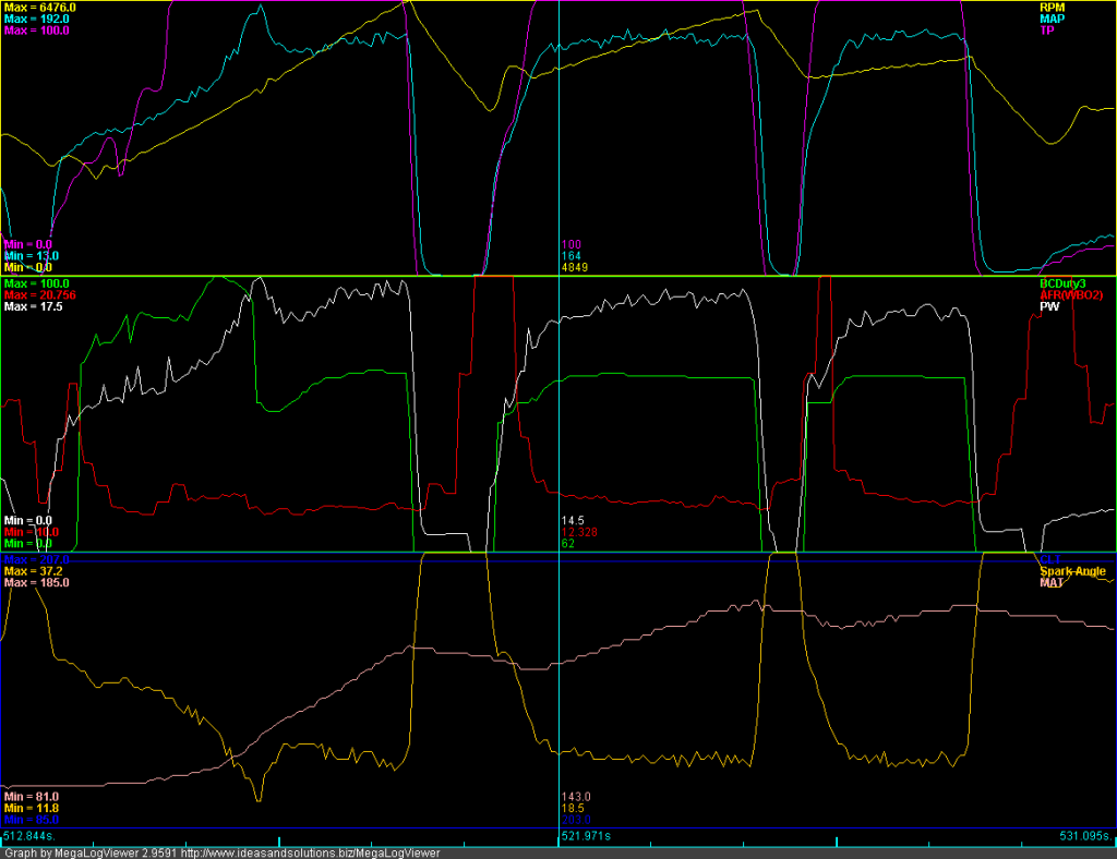
Well, the above just doesn't make sense for proportional-only control. Why would proportional-only control overshoot at modest gain settings? Why would it be so dependent upon the rate of RPM change? Why would proportional-only control exhibit what looks exactly like integral windup (see how the duty cycle climbs to and gets to 100% right before saying "oh, oh" and dropping like a rock).
So, I opened the code (msns-extra.asm). Guess what? MS1/MSPNP CL EBC isn't proportional at all. In fact, it would properly be described as Integral + Derivative. The so called "Proportional Gain" is really an integral gain . . . it adjusts how fast the integrator responds when off setpoint. The equation is:
DC = DC + "Proportional Gain" x ( kPa Target - kPa ) - "Differential Gain" x ( kPa - kPa_previous )
Since the control is mainly integral, a different tuning strategy is required. Fortunately, we've got effective tools available -- although the way we'll use some of the parameters will be a little "different." I feel another long-winded tuning explanation coming on. But, like President Obama, I'm going to present it AFTER vacation.
In the meantime, here's the same 2-3-4 with proper tuning to whett your appetite:
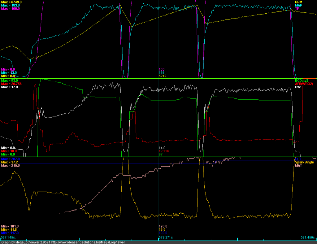
Hustler, I'm asking 3 beers and a track ride to tune your closed loop EBC.

Well, the above just doesn't make sense for proportional-only control. Why would proportional-only control overshoot at modest gain settings? Why would it be so dependent upon the rate of RPM change? Why would proportional-only control exhibit what looks exactly like integral windup (see how the duty cycle climbs to and gets to 100% right before saying "oh, oh" and dropping like a rock).
So, I opened the code (msns-extra.asm). Guess what? MS1/MSPNP CL EBC isn't proportional at all. In fact, it would properly be described as Integral + Derivative. The so called "Proportional Gain" is really an integral gain . . . it adjusts how fast the integrator responds when off setpoint. The equation is:
DC = DC + "Proportional Gain" x ( kPa Target - kPa ) - "Differential Gain" x ( kPa - kPa_previous )
Since the control is mainly integral, a different tuning strategy is required. Fortunately, we've got effective tools available -- although the way we'll use some of the parameters will be a little "different." I feel another long-winded tuning explanation coming on. But, like President Obama, I'm going to present it AFTER vacation.

In the meantime, here's the same 2-3-4 with proper tuning to whett your appetite:

Hustler, I'm asking 3 beers and a track ride to tune your closed loop EBC.

Last edited by hornetball; 09-13-2011 at 04:57 PM.
Thread
Thread Starter
Forum
Replies
Last Post
Lincoln Logs
Dynos and timesheets
4
09-23-2015 01:26 PM
FAB
Fab9 Tuning - Miata Performance Parts
0
09-11-2015 01:02 PM


