
MS wiring questions - fan control and CEL
 07-21-2013, 01:56 PM
#1

I have a '90 with Greddy Turbo, with a DIYautotune MS-1 Extra. I bought the MS used, didn't build it myself.
The car is currently running. MS install details:
- PCB v3.0
- piggyback to an oem ecu
- LC-1 wideband, wired to oem ecu input
- MAF delete
- GM IAT sensor is wired direct to MS
1. I did a coolant reroute with water neck delete, and I cannot get the MS to activate the fans. I've double-checked the settings for the temp activated JS3 output, which are correct insofar as they match what people have posted on the forum. The fans do work if I ground the thermoswitch lead or the appropriate diagnostic terminal, so I know the fans work and relay is fine. I've also tried turning on every other MS output, in case mine is wired differently, but no luck there.
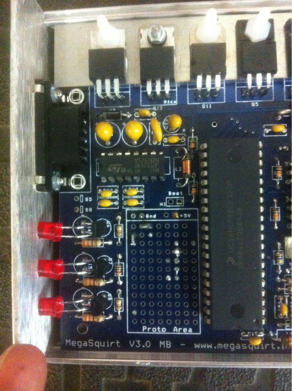
So, today when I get to the shop, I'll open up the MS to see if it needs a modification for the fan output. Question is - what should I be looking for? As I understand, I should see a different FET wired in place of the middle LED transistor and then a jumper from that LED to somewhere else? Can someone clarify and/or send a picture?
2. I want my CEL to work as much as possible, or to at least look like it works properly (e.g. turn on for a few seconds at startup). Am I right in thinking that I could accomplish this with the following two changes-
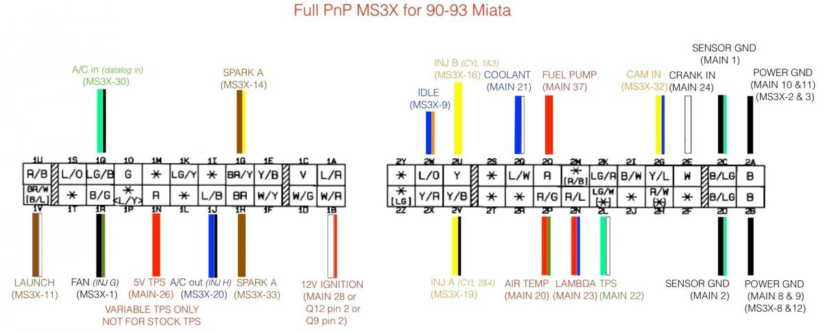
A. Wire the LC-1 direct to the MS (pinout 23 on the 47 pin connector) and then rewire my narrowband o2 back to where it belongs on the oem ecu.
B. tap into the IAT signal wire and connect it into the oem ecu (which pinout should that be?) so that the computer 'sees' an appropriate resistor range and thinks I still have an AFM.
?
The car is currently running. MS install details:
- PCB v3.0
- piggyback to an oem ecu
- LC-1 wideband, wired to oem ecu input
- MAF delete
- GM IAT sensor is wired direct to MS
1. I did a coolant reroute with water neck delete, and I cannot get the MS to activate the fans. I've double-checked the settings for the temp activated JS3 output, which are correct insofar as they match what people have posted on the forum. The fans do work if I ground the thermoswitch lead or the appropriate diagnostic terminal, so I know the fans work and relay is fine. I've also tried turning on every other MS output, in case mine is wired differently, but no luck there.
So, today when I get to the shop, I'll open up the MS to see if it needs a modification for the fan output. Question is - what should I be looking for? As I understand, I should see a different FET wired in place of the middle LED transistor and then a jumper from that LED to somewhere else? Can someone clarify and/or send a picture?
2. I want my CEL to work as much as possible, or to at least look like it works properly (e.g. turn on for a few seconds at startup). Am I right in thinking that I could accomplish this with the following two changes-
A. Wire the LC-1 direct to the MS (pinout 23 on the 47 pin connector) and then rewire my narrowband o2 back to where it belongs on the oem ecu.
B. tap into the IAT signal wire and connect it into the oem ecu (which pinout should that be?) so that the computer 'sees' an appropriate resistor range and thinks I still have an AFM.
?

Reply
 0
0

0
 07-21-2013, 03:25 PM
#4
Thanks for taking the time to post your helpful response. I've done hours of research and hundreds of searches just to be able to phrase the questions I've asked. You may have noticed that I've been extremely detailed and specific - really I'm only asking for confirmation that my understanding is correct.
Or were you too lazy of a **** to read my post?
Or were you too lazy of a **** to read my post?
Reply
0
0
07-21-2013, 04:28 PM
#6
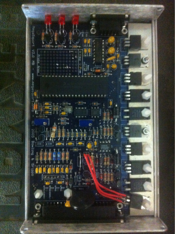
Okay, got to the shop, pulls the megasquirt, and opened her up. It is indeed PCB v3.0 (I never was 100% sure). It looks like the middle led is indeed wired up the "stock" way.
So I think this confirms that to activate my fan with MS I need to do the middle LED mod? If so, is ZTX450 the correct transistor? I do not have the spare Q4 transistor as I just bought the assembled MS.
So I think this confirms that to activate my fan with MS I need to do the middle LED mod? If so, is ZTX450 the correct transistor? I do not have the spare Q4 transistor as I just bought the assembled MS.
Reply
0
0
 07-22-2013, 06:03 AM
#8
Newb

Join Date: Jul 2013
Posts: 16
Total Cats: -1
Last edited by dinoman; 07-22-2013 at 07:34 AM.
Reply
0
0
07-22-2013, 06:37 AM
#9
Senior Member

Join Date: Nov 2007
Location: Belgium
Posts: 999
Total Cats: 73
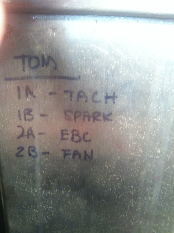
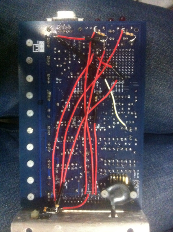
It seems from what's written on your unit, that IAC2B is wired as the fan output, not IAC2A, so I'd run the wire from the top hole of D15 to iac2B instead of iac2A as suggested above. That's pin 31 on the db37. You should have a wire in your loom going from DB37 pin 31 to mazda connector pin 1R (Black/green).
Reply
0
0
07-22-2013, 07:12 AM
#10
Boost Czar


iTrader: (62)
Join Date: May 2005
Location: Chantilly, VA
Posts: 79,729
Total Cats: 4,126
Whomever you bought it from, removed the transistors that I put in the proto area 6 years ago.
That would have connected the JS0 circuit to provide the fan control...
That would have connected the JS0 circuit to provide the fan control...
Reply
0
0
01-03-2014, 01:45 AM
#11
Update: all issues resolved!
Braineack's original JSO circuit was still in place (transistor is just impossible to see in that poorly lit photo). The pin 29 output wasn't wired up to anything, so I connected that to Pin 1R on the mazda connector.
On CELs, I did the following:
- wired LC1 wideband output directly to MS pin 23
- connected oem narrowband (I'm still running both o2 sensors just in case) output back to the oem ECU (pin 2N)
- connected the AIT output to the oem ECU "air temp" pin 2P. This seems to put out a sufficiently plausible signal to fool my obd1 ecu. No check engine light!
While I was in there, I went ahead and ran a lead from the MS pin 31 for Electronic Boost Control - can never be too ready, right?
All the above seems very simple in retrospect - shame on me for not reading up and fully understanding what I was doing. That said, I'm sure I'll be asking for tuning help soon :P
Reply
0
0

Thread
Thread Starter
Forum
Replies
Last Post
Zaphod
MEGAsquirt
47
10-26-2018 11:00 PM
StratoBlue1109
Miata parts for sale/trade
21
09-30-2018 01:09 PM
Greasyman
General Miata Chat
2
09-28-2015 10:44 AM


