
Learn me how to seq. injectors
 10-31-2012, 08:42 PM
#1
Senior Member
Thread Starter
iTrader: (5)

Join Date: Sep 2009
Location: Lompoc, CA
Posts: 577
Total Cats: 13
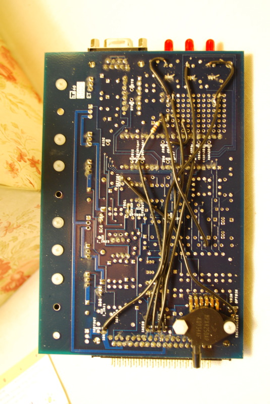
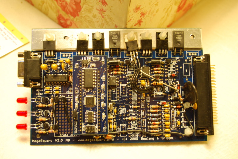
So, I've been digging through schematics and researching for quite a while now trying to learn how to make my MS2 have sequential injection. I didn't assemble this board and I've just hit a brick wall with all of the possibilities. I know that my particular MS2 only has 2 injector drivers. I know how to solder to a board, and how most electronics components work. What I don't know is exactly what I need to install or connect to where to get sequential injection working. I know for sequential ignition I would need a crank position sensor. But the CAS is sufficient for injection, correct? So here are some pics of what I'm working with. Can I make this work in the proto area with some simple components? Do I need to buy the diypnp doo-dad on diyautotune's site? Someone help me out please. I can provide more detailed pictures or descriptions if needed.

Reply
 0
0

0
11-01-2012, 08:48 AM
#3
Boost Czar


iTrader: (62)
Join Date: May 2005
Location: Chantilly, VA
Posts: 79,729
Total Cats: 4,126
Basically all 4 injectors need the same driver. It's easier if you build 4 new injector drivers circuits at the same time.
I like to copy the circuit on the DIYPNP/MS3X, which uses 1 driver and 2 resistors each. Very simply and works well.
But to make life even easier, you could buy this board: 4-Channel Ignition/Injection Driver Board
and follow the documenation here: Sequential Injection Code for MS2
read through it like 4-5 times.
Reply
0
0
 Obeezy
11-01-2012, 11:03 AM
Obeezy
11-01-2012, 11:03 AM
#6
Senior Member
Thread Starter
iTrader: (5)
Join Date: Sep 2009
Location: Lompoc, CA
Posts: 577
Total Cats: 13
Sweet, thanks for the help Brain. My awesome gub'ment network won't let me check the second link at work. I'll have a look when I get home. But it looks like that is exactly the information I needed to make this work.
Reply
0
0
11-01-2012, 11:06 AM
#7
Boost Czar
iTrader: (62)
Join Date: May 2005
Location: Chantilly, VA
Posts: 79,729
Total Cats: 4,126
weird, it's the same server.
I have to use a token to view, myself. But I cant access the second...It wont load if you open in a second tab, but it will if I load in the same tab I logged in with.
I have to use a token to view, myself. But I cant access the second...It wont load if you open in a second tab, but it will if I load in the same tab I logged in with.
Reply
0
0
11-01-2012, 02:17 PM
#8
Senior Member
Thread Starter
iTrader: (5)
Join Date: Sep 2009
Location: Lompoc, CA
Posts: 577
Total Cats: 13
So if I understand correctly, I can use this schematic for the MS3x. I build 2 more injector driver circuits (assuming these already match the existing 2) or build 4 new ones with the same components. I jump the FET output to the corresponding pins on the 37 pin ouput connector. But where do I pull the injector number 3 and 4 FET inputs from? It would be PA2 and PA3 on the diagram? I really hate to pay $50 for a board and $5 in components when I have the capability to make my own circuit boards if I need to. Either that, or shouldn't I be able to use the on board proto area and then sink the FET's to the case like the others?

Reply
0
0
11-01-2012, 02:19 PM
#9
Boost Czar
iTrader: (62)
Join Date: May 2005
Location: Chantilly, VA
Posts: 79,729
Total Cats: 4,126
all four drivers need to match. so if you build the above, you need to build all 4.
if you read the docs I posted, it explains where the outputs go. you have to mod the ms2 daughterboard and remove the cpu clock circuit from the mainboard (not really all of it, just the components touching a certain spot).
here:
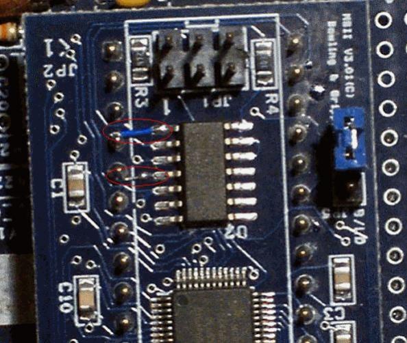
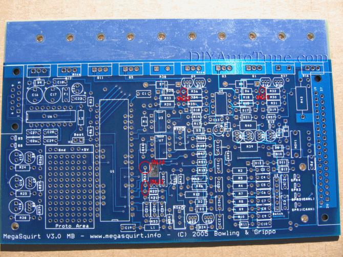
The picture below shows the placement on the V3.0 board of the 4 injector channels. The standard injector drivers components can be left on the board but will be unused and will not interfere with injector channels 1 and 2. The injectors channels 3 and 4 connect to pads originally used for the MS1 clock circuit and require the removal of those components for proper and safe operation. The injector channel 3 shows 2 pads because they correspond to the same electrical location (use either one). The components to remove are: R21,C20,C21,R22,R23,Y1,C24,C25.
if you read the docs I posted, it explains where the outputs go. you have to mod the ms2 daughterboard and remove the cpu clock circuit from the mainboard (not really all of it, just the components touching a certain spot).
here:
The picture below shows the placement on the V3.0 board of the 4 injector channels. The standard injector drivers components can be left on the board but will be unused and will not interfere with injector channels 1 and 2. The injectors channels 3 and 4 connect to pads originally used for the MS1 clock circuit and require the removal of those components for proper and safe operation. The injector channel 3 shows 2 pads because they correspond to the same electrical location (use either one). The components to remove are: R21,C20,C21,R22,R23,Y1,C24,C25.
Reply
0
0
11-08-2012, 01:04 PM
#11
Senior Member
Thread Starter
iTrader: (5)
Join Date: Sep 2009
Location: Lompoc, CA
Posts: 577
Total Cats: 13
Assuming that part is correct, where do I connect the drain of the fet to the board for each injector.
When that's all done, I'll have to rewire pins 32-35 to the car harness so that injector 1 from the ecu fires cylinder 1, and injector 2 fires cylinder 3, and so on according to the firing order correct?
Reply
0
0

Thread
Thread Starter
Forum
Replies
Last Post
StratoBlue1109
Miata parts for sale/trade
21
09-30-2018 01:09 PM


