
Installing MS2 on 99
 02-12-2012, 12:34 PM
#42
Boost Czar


iTrader: (62)
Join Date: May 2005
Location: Chantilly, VA
Posts: 79,729
Total Cats: 4,126
please don't arbitrarily change my settings, the basemap was setup exactly for YOUR ms. It shares little in common with a DIYPNP.
It actually appears as though I swapped the ckp/cmp inputs on the harness.
It actually appears as though I swapped the ckp/cmp inputs on the harness.

Reply
 0
0

0
02-12-2012, 12:40 PM
#43
Senior Member
Thread Starter
iTrader: (14)

Join Date: Oct 2006
Location: South East Florida
Posts: 677
Total Cats: 6
If you're running the stock Mazda ignition (meaning you haven't installed coil-on-plug ignition or anything) then use DIY's igntion settings exactly.
Any luck with the TPS? You need to have that working because right now your MS is reading 100%. The default setting for "flooding clear mode" is 70% so if the MS sees a throttle position above that it will not inject any fuel.
Any luck with the TPS? You need to have that working because right now your MS is reading 100%. The default setting for "flooding clear mode" is 70% so if the MS sees a throttle position above that it will not inject any fuel.
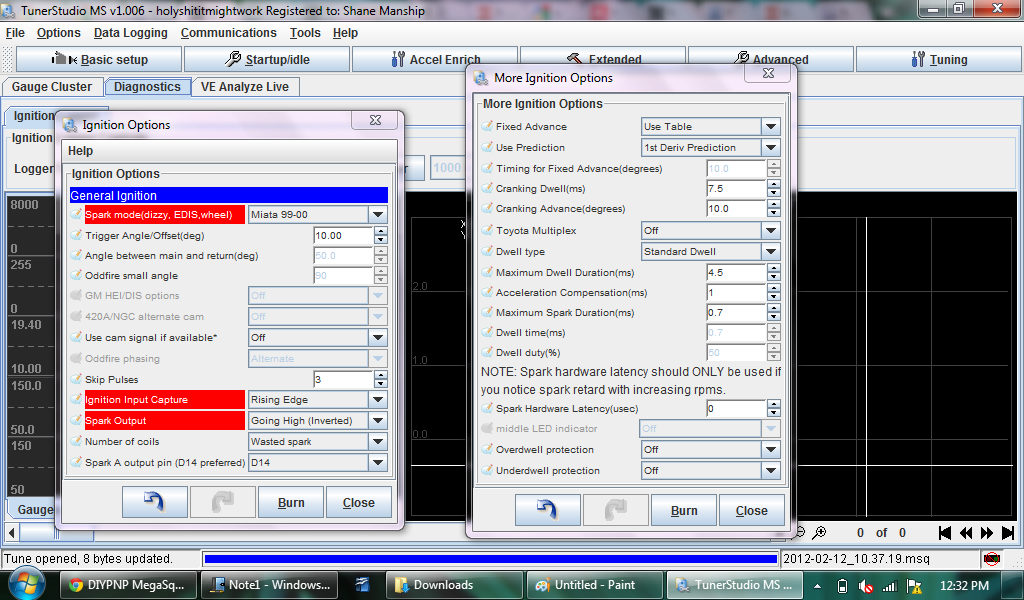
Went ahead and changed to DIY's ignition settings. Could not find anything for:
- skip pules - box on left
- spark A output pin
- fixed advance - box on right
- use prediction
Great point on the flood clear. Tried to change it to 110% to take away authority, and it does not allow.
Can not set the TPS at all. It reads 1023 no matter where the pedal is pressed.
Reply
0
0
02-12-2012, 12:54 PM
#47
Junior Member

Join Date: Feb 2011
Posts: 51
Total Cats: 2
Why not reload Brain's map and see what can be done with it? You have plenty of time before tomorrow & can still mail it out if need be.
Might as well learn by doing, then in the future you will have an idea of how everything works if something goes wrong instead of having to mail off your MS every time...
Might as well learn by doing, then in the future you will have an idea of how everything works if something goes wrong instead of having to mail off your MS every time...
Reply
0
0
02-28-2012, 01:19 PM
#49
Senior Member
Thread Starter
iTrader: (14)
Join Date: Oct 2006
Location: South East Florida
Posts: 677
Total Cats: 6
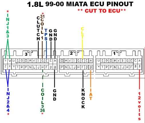
Brain swapped 3J and 3H, the two Cam inputs. He also checked the CLT and TPS, which both worked fine on the stim.
CLT and TPS are still not connecting properly. I directly connected red/blue on 2E from this wiring diagram to the Yellow 2E on the pinout below, and it is still not reading coolant temp.
Scott is thinking they share a ground and it could be faulty. Any idea where this ground is located?
Any other ideas??
Reply
0
0
02-28-2012, 01:45 PM
#51
Boost Czar
iTrader: (62)
Join Date: May 2005
Location: Chantilly, VA
Posts: 79,729
Total Cats: 4,126
Yeah, I'm a bit clueless on this. I did mistakenly have the cam/crank inputs crossed on the harness like I suspected after seeing the composite log posted by Shane. I corrected this.
But I know the TPS and CLT were wired correcly on the harness and functioned fine on the stim, but I checked it against 3 different diagrams to be certain--plus those functions had always been working when it was an MSI and I didn't touch them when modding to MSII.
My only guess right now is that the ground in the engine bay is missing. Correct me if I'm wrong, but I'm pretty sure that would cause the CLT sensor to sit at 180�F (which is failsafe IIRC) and the TPS to sit at full 5v. Unless there's a ground in the engine harness I missed that's required,
...acutally now that I think about it I almost remember something to this matter. I think I did the three grounds above and not to the 3F as well, that may be what's missing here.
Yeah, now I'm pretty certain that's the issue.
Reply
0
0
03-01-2012, 01:38 PM
#52
Senior Member
Thread Starter
iTrader: (14)
Join Date: Oct 2006
Location: South East Florida
Posts: 677
Total Cats: 6
The missing ground was the problem. All sensors are reading now!
I have made two attempts at starting, and it has not fired up yet. Attached is datalog, msq, and .ini.
Let's get her started!!!! (help me please)
edit: I guess I can not upload the .ini
I have made two attempts at starting, and it has not fired up yet. Attached is datalog, msq, and .ini.
Let's get her started!!!! (help me please)
edit: I guess I can not upload the .ini
Reply
0
0
03-01-2012, 02:09 PM
#54
Senior Member
Thread Starter
iTrader: (14)
Join Date: Oct 2006
Location: South East Florida
Posts: 677
Total Cats: 6
Yes, I am getting RPM. Reads around 160 while cranking.
For some wierd reason, I can not open the composit logger. It is greyed out, and I can not click on it. Will try to reboot everything and try again.
For some wierd reason, I can not open the composit logger. It is greyed out, and I can not click on it. Will try to reboot everything and try again.
Reply
0
0
03-01-2012, 02:23 PM
#56
Senior Member
Thread Starter
iTrader: (14)
Join Date: Oct 2006
Location: South East Florida
Posts: 677
Total Cats: 6
Is this far too rich? I have req fuel at 11.9, and I am still using the stock 99 injectors.
Whats up with the GEGO?
Also surprised where the MAP sits.
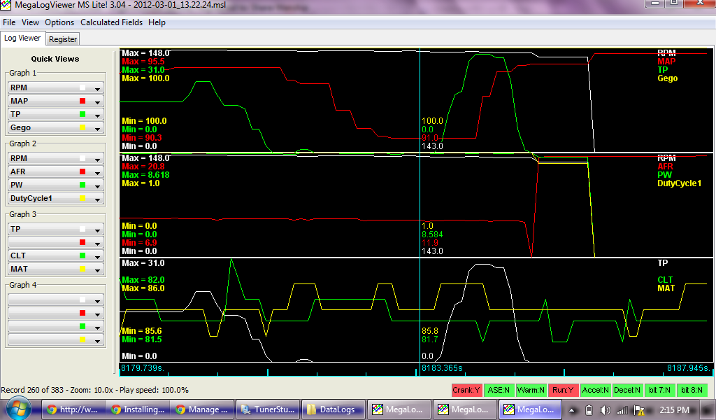
Whats up with the GEGO?
Also surprised where the MAP sits.
Reply
0
0
03-01-2012, 02:51 PM
#58
Senior Member
Thread Starter
iTrader: (14)
Join Date: Oct 2006
Location: South East Florida
Posts: 677
Total Cats: 6
Not really. I put jumper cables on to up the charge, and still spun at that speed.
I also lowered cranking speed in the settings to 160 as well as lowered cranking pulsewidth.
I also lowered cranking speed in the settings to 160 as well as lowered cranking pulsewidth.
Reply
0
0
03-01-2012, 03:12 PM
#60
Elite Member
iTrader: (10)
Join Date: Jun 2006
Location: Athens, Greece
Posts: 5,990
Total Cats: 361
The actual cranking speed is low, get a decent battery. You are not pulling enough vacuum and your cranking pulsewidth is also low if you still have the stock injectors in.
Reply
0
0


