
I get bored easily.
 01-27-2012, 01:17 PM
#61
Boost Pope


Thread Starter
iTrader: (8)
Join Date: Sep 2005
Location: Chicago. (The less-murder part.)
Posts: 33,485
Total Cats: 6,898
Jason, I've read through that last post of yours twice, and I'm not 100% certain whether you are trying to:
A: Argue against something I have said earlier,
B: Speak in support of something I have said earlier, or
C: Introduce an entirely new vector to the conversation.
The best I have been able to make out goes something like this:
"Having a ground path for the analog sensors which is separate from the ground path for the high-current drivers is good. It's better if the sensors ground directly to the ECU rather than to some common-point external to the ECU."
Is that pretty much on-target?

Reply
 0
0

0
01-27-2012, 07:22 PM
#62
Elite Member

Join Date: Jul 2005
Posts: 6,420
Total Cats: 84
B: Speak in support of something I have said earlier,
C: Introduce an entirely new vector to the conversation.

Reply
0
0
01-27-2012, 07:50 PM
#63
Boost Pope
Thread Starter
iTrader: (8)
Join Date: Sep 2005
Location: Chicago. (The less-murder part.)
Posts: 33,485
Total Cats: 6,898
Check.
Yes, regarding the use of a 0.7Ω polyfuse. I explained how it's better than shorting out said polyfuse (i.e. 2 grounds connected together on PCB)
Insofar as noise isolation (preventing noise generated by high-current devices from influencing the readings of analog sensors) having any kind of connection whatsoever between the two ground planes within the ECU cannot, under any "normal" circumstances, be superior to having no connection whatsoever between them.
And since I have no updated images for today, here is a picture of a man with entirely too many pieces of analog test gear holding a cat:
Reply
0
0
01-27-2012, 08:19 PM
#64
Elite Member
Join Date: Jul 2005
Posts: 6,420
Total Cats: 84
IOW I was splainin their thinking. It's like my suggestion of using a 10 Ω polyfuse but they used a 0.7 Ω one instead.
Insofar as noise isolation (preventing noise generated by high-current devices from influencing the readings of analog sensors) having any kind of connection whatsoever between the two ground planes within the ECU cannot, under any "normal" circumstances, be superior to having no connection whatsoever between them.
And since I have no updated images for today, here is a picture of a man with entirely too many pieces of analog test gear holding a cat:
Reply
0
0
01-27-2012, 08:31 PM
#65
Junior Member

Join Date: Sep 2011
Location: finger lakes NY
Posts: 433
Total Cats: 17
Jason, thanks for all the explanations of all the different scenarios... But I have a question and I think it's the same thing that Joe is trying to say as a statement.
Suppose I design an ECU with completely separate grounds for analog and high current stuff; two separate ground wires going to the engine. Then, someone comes along and says "you should put a polyfuse in the ECU connecting those two grounds." Here's the question: why would I wanna do that?
Suppose I design an ECU with completely separate grounds for analog and high current stuff; two separate ground wires going to the engine. Then, someone comes along and says "you should put a polyfuse in the ECU connecting those two grounds." Here's the question: why would I wanna do that?
Reply
0
0
01-28-2012, 12:00 AM
#66
Elite Member
Join Date: Jul 2005
Posts: 6,420
Total Cats: 84
As I typed in an earlier post  , in case the user forgets one of the ground wires. If the logic/analog ground wire is forgotten, it will work but there will be sensor noise. The user will then post here saying "my signals are noisy", and then someone will reply "search, newbie!", then he'll find a post saying "you forgot the other ground wire". If the high current ground wire is forgotten, the unit might cycle on and off, he will post here, and get the same reply.
If the grounds are completely one ground wire is forgotten, the MOSFETs may be put in a half on half off state and they will overheat. Or if the designer used Schmitt trigger inputs for the MOSFET signals, one subcircuit may "motorboat" ... more unpredictable.
, in case the user forgets one of the ground wires. If the logic/analog ground wire is forgotten, it will work but there will be sensor noise. The user will then post here saying "my signals are noisy", and then someone will reply "search, newbie!", then he'll find a post saying "you forgot the other ground wire". If the high current ground wire is forgotten, the unit might cycle on and off, he will post here, and get the same reply. If the grounds are completely one ground wire is forgotten, the MOSFETs may be put in a half on half off state and they will overheat. Or if the designer used Schmitt trigger inputs for the MOSFET signals, one subcircuit may "motorboat" ... more unpredictable.
Reply
0
0
01-28-2012, 12:13 AM
#67
Elite Member
Join Date: Jul 2005
Posts: 6,420
Total Cats: 84
Oh, and Joe, I forgot the other half of the technique for keeping the noise out. You have to keep the 12V feeding the 2 subcircuits separate too (assuming you have circuitry powered by 12V for the high current stuff also). This step is often forgotten. Each subcircuit has its own power supply decoupling capacitor (e.g. 1000 uF / 16V) between its local 12V and local ground. And here is the secret bit - each capacitor is fed from the main 12V line from the car via a 0.33Ω resistor (or some other value depending on how much current the subcircuits need). If you have some hi current pullup MOSFETs on your board these won't have a 1Ω resistor. The purpose of the 1Ω resistors is to prevent power supply noise due to pulsating power supply current demands in one subcircuit from going to the other subcircuit(s). If you omit this, additionally, the noise current will flow down one ground wire, up the other, producing a voltage drop on the logic/analog ground wire, appearing as noise on the analog sensor signals. I've fixed many designs that were caused by omitting the resistors.
Reply
0
0
01-28-2012, 01:56 AM
#68
Boost Pope
Thread Starter
iTrader: (8)
Join Date: Sep 2005
Location: Chicago. (The less-murder part.)
Posts: 33,485
Total Cats: 6,898
- The 5v regulator (linear)
- The fuel pump driver (an AQV252G opto-relay)
- The injector driver (an IXDI404 gate driver)
- Various flybacks
The "delicate" 5v feeds (the processor's VDDA and the +5 analog reference voltage) are further refined with an LC filter.
The IXDI404 also has a diode between it and +12, again with a capacitor after it. So it, too, will be relatively immune to pulsation in the +12 supply.
And the two ground planes are still completely isolated all the way to the engine.
I've been playing Team Fortress 2 all night rather than working, so here is a cat named Zener standing on a 555:
Reply
0
0
01-30-2012, 02:02 PM
#70
Boost Pope
Thread Starter
iTrader: (8)
Join Date: Sep 2005
Location: Chicago. (The less-murder part.)
Posts: 33,485
Total Cats: 6,898
So I spent a bit of time over the weekend thinking about what you (Jason) said earlier about the analog filtering. I took a look at what they'd done on the rev 3.0 MS board, and was kind of surprised at how tiny the RC filters were- like 2.2ms on the temp sensors, and 220us on the MAP, O2 and TPS.
I decided to give some larger values a try.
Large-value, low-tolerance ceramics aren't especially easy to come by, however I happened to have a bag of 10uf 10v 1206 surface-mount caps lying around, so I tacked some of those to the backside of all of the existing filter caps I had installed, and increased the values of R to 2.49k for MAP and the two O2 sensors, and 100k for the two temp sensors. I left TPS at 1k.
That should give me 25ms on the MAP and O2, 10ms on TPS, and a full second on CLT and IAT. ( I want TPS to be especially responsive, as I intend to use it for Accel. Once I get an analog TPS, of course.)
We'll see how this does.
I'm still struggling with this concept.
I agree about the D+C filtering to separate individual consumers of +12, and I have done this in the places where they are likely to be sensitive to ripple in this line (the flybacks and the fuel pump relay probably won't care.)
What I'm still not grasping is how the distribution of grounds has any effect on the above.
Take the following hypothetical, where I've simplified the +5 regulator, the PWM idle driver and the injector driver by removing all filtration and isolation from them. +12 is the raw supply from the car, and AGND and IGND are the two separate grounds which are isolated all the way down to the engine itself.
The operation of the idle driver is simplicity itself. The CPU applies voltage to Q4 (a darlington) and current is conducted from the idle valve down to IGND. A tiny amount of current also flows from the CPU out through the base-emitter junction of Q4 to IGND. I see no way for this to cause noise or other unpleasantness on the analog side of the device.
At the Injector driver, I can see a potential fault with what I have right now. During the turn-on phase, a bit of current flows from +12 through the gate driver and into Q1, then down to IGND. No problems there. During the turn-off phase, however, I suppose that a bit of current is going to sink from Q1 through the driver and down to AGND, and that could potentially cause some ripple on the AGND line. I should probably move that ground to IGND.
What I fail to see, in any case, is how conjoining AGND and IGND with any kind of resistive device would improve the situation. In the above example, any current coming back through the driver chip to AGND is going to stay on the AGND wire rather than crossing over through whatever resistor or polyfuse might be in place between the two grounds.
I decided to give some larger values a try.
Large-value, low-tolerance ceramics aren't especially easy to come by, however I happened to have a bag of 10uf 10v 1206 surface-mount caps lying around, so I tacked some of those to the backside of all of the existing filter caps I had installed, and increased the values of R to 2.49k for MAP and the two O2 sensors, and 100k for the two temp sensors. I left TPS at 1k.
That should give me 25ms on the MAP and O2, 10ms on TPS, and a full second on CLT and IAT. ( I want TPS to be especially responsive, as I intend to use it for Accel. Once I get an analog TPS, of course.)
We'll see how this does.
I agree about the D+C filtering to separate individual consumers of +12, and I have done this in the places where they are likely to be sensitive to ripple in this line (the flybacks and the fuel pump relay probably won't care.)
What I'm still not grasping is how the distribution of grounds has any effect on the above.
Take the following hypothetical, where I've simplified the +5 regulator, the PWM idle driver and the injector driver by removing all filtration and isolation from them. +12 is the raw supply from the car, and AGND and IGND are the two separate grounds which are isolated all the way down to the engine itself.
The operation of the idle driver is simplicity itself. The CPU applies voltage to Q4 (a darlington) and current is conducted from the idle valve down to IGND. A tiny amount of current also flows from the CPU out through the base-emitter junction of Q4 to IGND. I see no way for this to cause noise or other unpleasantness on the analog side of the device.
At the Injector driver, I can see a potential fault with what I have right now. During the turn-on phase, a bit of current flows from +12 through the gate driver and into Q1, then down to IGND. No problems there. During the turn-off phase, however, I suppose that a bit of current is going to sink from Q1 through the driver and down to AGND, and that could potentially cause some ripple on the AGND line. I should probably move that ground to IGND.
What I fail to see, in any case, is how conjoining AGND and IGND with any kind of resistive device would improve the situation. In the above example, any current coming back through the driver chip to AGND is going to stay on the AGND wire rather than crossing over through whatever resistor or polyfuse might be in place between the two grounds.
Reply
0
0
01-30-2012, 03:09 PM
#71
Supporting Vendor

iTrader: (33)
Join Date: Jul 2006
Location: atlanta-ish
Posts: 12,659
Total Cats: 134
What I fail to see, in any case, is how conjoining AGND and IGND with any kind of resistive device would improve the situation. In the above example, any current coming back through the driver chip to AGND is going to stay on the AGND wire rather than crossing over through whatever resistor or polyfuse might be in place between the two grounds.
Reply
0
0
01-30-2012, 03:31 PM
#72
Boost Pope
Thread Starter
iTrader: (8)
Join Date: Sep 2005
Location: Chicago. (The less-murder part.)
Posts: 33,485
Total Cats: 6,898
Yeah, I understand that.
I was referring specifically to Jason's assertion that "no two subcircuits with separate grounds, should have their 12V supply connected to each other, without individual D+C or R+C 12V filtering."
I can't see how the presence or absence of such filtration and the combining or splitting of the grounding system are in any way related to one another.
Reply
0
0
01-30-2012, 03:46 PM
#73
Supporting Vendor
iTrader: (33)
Join Date: Jul 2006
Location: atlanta-ish
Posts: 12,659
Total Cats: 134
Yeah, I understand that.
I was referring specifically to Jason's assertion that "no two subcircuits with separate grounds, should have their 12V supply connected to each other, without individual D+C or R+C 12V filtering."
I can't see how the presence or absence of such filtration and the combining or splitting of the grounding system are in any way related to one another.
I was referring specifically to Jason's assertion that "no two subcircuits with separate grounds, should have their 12V supply connected to each other, without individual D+C or R+C 12V filtering."
I can't see how the presence or absence of such filtration and the combining or splitting of the grounding system are in any way related to one another.
Reply
0
0
01-30-2012, 11:44 PM
#75
Elite Member
Join Date: Jul 2005
Posts: 6,420
Total Cats: 84
Here you go.
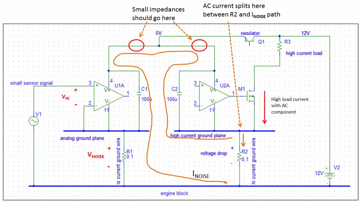
The 2 "opamps" are subcircuits, on 2 different ground planes. They each have a 100 uF VCC bypass cap. Their VCC's are connected together (the no-no). Each ground plane has a ground wire connecting to the engine block, represented by 2 0.1 Ω resistors to the engine block. V1 represents a sensor output voltage.
When VCC is shared between 2 subcircuits with different ground potentials, and with a VCC bypass cap, they need to be separated by some impedance.
See schematic below. The high current through the load always has an AC component, e.g. the step components in injector currents. The AC current flows down through the MOSFET, through the high current ground plane, and splits between the high current ground wire and the two 100 uF bypass caps. If the tops of the bypass caps are connected together, they effectively connect the 2 ground planes with a low impedance (to AC), just like if you shorted them. The noise current flows down analog ground wire which develops a voltage across it. This voltage appears in the analog input stage U1A. It sees as the input voltage, Vin = V1 + Vnoise.
To prevent this problem there have to be impedances in the circled spots, which are greater than the impedance of R1. Better, you have a local regulator for the local 5V in each ground plane. Or, return the sensor to the analog ground plane and not the engine block.
This analysis is also relevant whenever you have some PCB trace lengths between the ground node of 2 circuits, to some common ground point or plane, and a small signal is referenced to said plane or point.
To analyze a connection between the 2 ground planes, connect them together with a low impedance.
Reply
0
0
01-31-2012, 01:06 AM
#76
Boost Pope
Thread Starter
iTrader: (8)
Join Date: Sep 2005
Location: Chicago. (The less-murder part.)
Posts: 33,485
Total Cats: 6,898
Ok, now I understand what's been gnawing at you.
That should not be a problem here, as I do not have IGND capacitively coupled to +5 or to AGND anywhere.
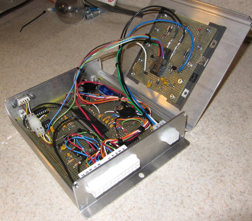
In addition to being schematically separate from the main board, IGND is also physically separate from it. IGND exists only on the high-current board (the one with all of the TO-220 parts on it) and the only place where +5 shows up on that board is at the regulator, which is there simply because of the heat sink (from which it is electrically insulated.) For that purpose, I am carrying AGND to the regulator via the harness which interconnects the two boards. Electrically, the regulator is completely isolated from the rest of the high-current board.
The only place on the entire board where I see a potential for noise is gate current from the FETs sinking through the gate driver (which is on the main board) as pictured earlier, and I can solve that by bringing IGND across to the main board and connecting it to the gate driver instead of AGND. Once I make that move, then IGND will be capacitvely coupled to +12 (the only such place where this occurs), however there are, as I said before, blocking diodes between +12 and any circuit that's likely to care about a bit of ripple.
edit: Or, on second thought, I could just leave it alone. There's enough resistance between the gate driver and the FET that the reverse-current through there should not be too dramatic, and I'm going to err on the side of caution by respecting the datasheet's instruction that the GND pin "should be connected to a low noise analog ground plane for optimum performance." Everything seems pretty clean on the bench.
That should not be a problem here, as I do not have IGND capacitively coupled to +5 or to AGND anywhere.
In addition to being schematically separate from the main board, IGND is also physically separate from it. IGND exists only on the high-current board (the one with all of the TO-220 parts on it) and the only place where +5 shows up on that board is at the regulator, which is there simply because of the heat sink (from which it is electrically insulated.) For that purpose, I am carrying AGND to the regulator via the harness which interconnects the two boards. Electrically, the regulator is completely isolated from the rest of the high-current board.
The only place on the entire board where I see a potential for noise is gate current from the FETs sinking through the gate driver (which is on the main board) as pictured earlier, and I can solve that by bringing IGND across to the main board and connecting it to the gate driver instead of AGND. Once I make that move, then IGND will be capacitvely coupled to +12 (the only such place where this occurs), however there are, as I said before, blocking diodes between +12 and any circuit that's likely to care about a bit of ripple.
edit: Or, on second thought, I could just leave it alone. There's enough resistance between the gate driver and the FET that the reverse-current through there should not be too dramatic, and I'm going to err on the side of caution by respecting the datasheet's instruction that the GND pin "should be connected to a low noise analog ground plane for optimum performance." Everything seems pretty clean on the bench.
Last edited by Joe Perez; 01-31-2012 at 02:44 AM.
Reply
0
0
01-31-2012, 02:39 AM
#77
Elite Member
Join Date: Jul 2005
Posts: 6,420
Total Cats: 84
The IXDI chip bridges the 2 subsystems.
If you mount and ground it to the MOSFETs then the signal crosses the border. The driver input will see the noise voltage between the 2 grounds.
If you mount and ground it to the analog/logic system then the gate drive crosses the border. The MOSFET gate will see the noise voltage between the 2 grounds.
Of the 2, generally the first method is better, because MOSFETs tend to oscillate violently at high frequency when their driver is far away (stray inductances cause it). I described this in an earlier post.
The IXDI404 is way overkill for injector and solenoid MOSFETs. They are high speed drivers suited for driving 50A MOSFETs in 5 kW, 100 kHz switching power supplies. I would use 74C14 Schmitt triggers instead. You get 6 in a package, and you get the input noise rejection.
Reply
0
0
01-31-2012, 02:45 AM
#78
Elite Member
Join Date: Jul 2005
Posts: 6,420
Total Cats: 84
So I spent a bit of time over the weekend thinking about what you (Jason) said earlier about the analog filtering. I took a look at what they'd done on the rev 3.0 MS board, and was kind of surprised at how tiny the RC filters were- like 2.2ms on the temp sensors, and 220us on the MAP, O2 and TPS.
I decided to give some larger values a try.
Large-value, low-tolerance ceramics aren't especially easy to come by, however I happened to have a bag of 10uf 10v 1206 surface-mount caps lying around,
I decided to give some larger values a try.
Large-value, low-tolerance ceramics aren't especially easy to come by, however I happened to have a bag of 10uf 10v 1206 surface-mount caps lying around,
That should give me 25ms on the MAP and O2, 10ms on TPS, and a full second on CLT and IAT.
Reply
0
0
01-31-2012, 02:52 AM
#80
Boost Pope
Thread Starter
iTrader: (8)
Join Date: Sep 2005
Location: Chicago. (The less-murder part.)
Posts: 33,485
Total Cats: 6,898
I edited my post #76 above before I saw that you'd posted a reply.
Everything seems clean on the bench, so I'm going to try it as-is.
(Besides, it's all together and I'm feeling lazy.)
I present the Hellasquirt:
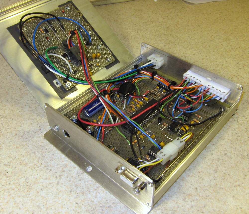
Everything seems clean on the bench, so I'm going to try it as-is.
(Besides, it's all together and I'm feeling lazy.)
I present the Hellasquirt:
Reply
0
0


