
I get bored easily.

 01-26-2012, 11:23 AM
#44
Elite Member

iTrader: (10)
Join Date: Jun 2006
Location: Athens, Greece
Posts: 5,990
Total Cats: 361
Just to let you know - the Enhanced MS2 that I build right now (the one based on the MS2V3), works like this - the medium and high current stuff is seperated, the MS2 mainboard only carries very low current signals and inputs. All the high current stuff (injectors, idle valve, boost control, relay control, etc) is done on my expansion board. In fact, I have seperate grounds on the expansion board for the high current devices and a seperate ground for the analog (and noise sensitive) devices.
Result is that with the standard MS2 code (no advanced TPS filtering) and with a TPSdot lag filter of 85, I'm getting TPSdot spikes that are not higher than about 20. Throttle response is SHARP.
Result is that with the standard MS2 code (no advanced TPS filtering) and with a TPSdot lag filter of 85, I'm getting TPSdot spikes that are not higher than about 20. Throttle response is SHARP.

Reply
 0
0

0
 01-26-2012, 11:38 AM
#46
Elite Member

Join Date: Jul 2005
Posts: 6,420
Total Cats: 84
Correct. It will be exactly identical to the way it's been working for the past 22 years on the stock ECU.
I, too, was present for the first day of class in DC Circuits 1.
Yeah, or I could just try the simple way first and see if it works before I double my parts-count to solve a problem which may not exist.
I, too, was present for the first day of class in DC Circuits 1.
Yeah, or I could just try the simple way first and see if it works before I double my parts-count to solve a problem which may not exist.
You also shouldn't forget the 10 Ω or so shunt resistor to link the 2 ground systems on your PCB.
Then when you're testing the system, examine the MOSFET Drain to Source voltage and check for oscillation, then examine your MAP sensor signal on the PCB and look for noise that is coincident with your injector signal.
Reply
0
0
01-26-2012, 02:38 PM
#51
Boost Pope

Thread Starter
iTrader: (8)
Join Date: Sep 2005
Location: Chicago. (The less-murder part.)
Posts: 33,485
Total Cats: 6,898
Just to let you know - the Enhanced MS2 that I build right now (the one based on the MS2V3), works like this - the medium and high current stuff is seperated, the MS2 mainboard only carries very low current signals and inputs. All the high current stuff (injectors, idle valve, boost control, relay control, etc) is done on my expansion board. In fact, I have seperate grounds on the expansion board for the high current devices and a seperate ground for the analog (and noise sensitive) devices.
Result is that with the standard MS2 code (no advanced TPS filtering) and with a TPSdot lag filter of 85, I'm getting TPSdot spikes that are not higher than about 20. Throttle response is SHARP.
Result is that with the standard MS2 code (no advanced TPS filtering) and with a TPSdot lag filter of 85, I'm getting TPSdot spikes that are not higher than about 20. Throttle response is SHARP.
I've seen some of your stuff, and I'm impressed. Honestly, what I'm doing here isn't all that fancy. I have decided that the ECU should control the check-engine light at startup (for smog-testing purposes), and since this car has aircon, I'm also experimenting with a new circuit for driving that. It's compatible with JustinHoMi's A/C idle-up code modification, and also lets the ECU automatically disengage the compressor if RPM falls below a certain threshold. Aside from that, I'm keeping things simple.
Reply
0
0
 01-26-2012, 05:02 PM
#54

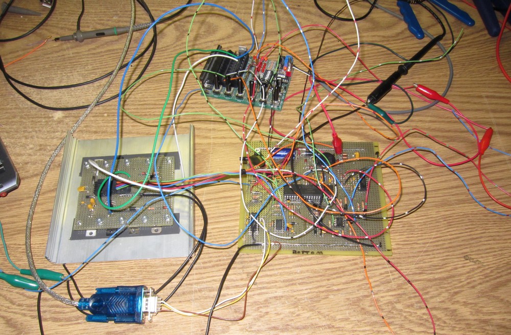
Progress pics. The sub-board has the power regulator along with all of the "noisy" stuff, which is basically the injector drivers and the IDL driver. They have their own dedicated grounds, completely isolated from the analog / logic grounds. (This is one of the design flaws in the 3.0 board that has always bothered me- everything shares a common ground.)
Thanks.
-Raj
Reply
0
0
01-26-2012, 05:16 PM
#55
Boost Pope
Thread Starter
iTrader: (8)
Join Date: Sep 2005
Location: Chicago. (The less-murder part.)
Posts: 33,485
Total Cats: 6,898
I don't want to cause anyone to blow up their MS3X, however at first glance, I see no harm in removing it, once you've made quite certain that your INJ GND pins are well coupled to ground.
Reply
0
0
01-26-2012, 09:37 PM
#56
I'm Miserable!

Join Date: Jun 2009
Location: albany, ga
Posts: 1,866
Total Cats: 0
Joe have you looked into FreeEMS? They have come long ways into getting a working EMS going and there is a few working and running installs already. Considering its all GPL you can build your own board and use their code without issues.
http://freeems.org/
http://freeems.org/
Reply
0
0
01-27-2012, 12:36 AM
#57
Elite Member
Join Date: Jul 2005
Posts: 6,420
Total Cats: 84
Yeah, I can't quite figure out why that polyfuse is there between the INJ GND and main ground on the MS3X board. When there's no current flowing across it, that polyfuse has a resistance of 0.5 to 0.77 ohms, so it's nearly the same as not having a separate ground in the first place.
Reply
0
0
01-27-2012, 01:45 AM
#58
Boost Pope
Thread Starter
iTrader: (8)
Join Date: Sep 2005
Location: Chicago. (The less-murder part.)
Posts: 33,485
Total Cats: 6,898
I can't see how conjoining the Inj GND and analog GND within the ECU itself has any effect whatsoever on how the CPU perceives the sensors. That is dictated by the wiring of the sensor grounds within the vehicle harness.
Perhaps you're not understanding the wiring of the 1.6 car? The analog ground is essentially a star topology. Essentially, all of the various sensor grounds and the ECU "analog" ground go to a central point (the aforementioned JC-02) and then from there to engine ground. The sensors are NOT grounded directly to the engine.
Conjoining the two ground planes within the ECU can only hurt the performance of the analog sensors. It can't help it.
Reply
0
0
 01-27-2012, 11:54 AM
#60
Elite Member
Join Date: Jul 2005
Posts: 6,420
Total Cats: 84
1) the 2 ground systems are kept separate except at that polyfuse point
and
2) the car's sensor grounds are returned only to the PCB, to the logic/analog ground and aren't connected to the engine ground along the way.
I understand that the 1.6 cars violate (2) above, and in that case, I explained that a 0.7Ω resistance is greater than the total resistance of the ground wires a) from the PCB high current ground to the 1.6 car high current ground lug, and b) the ground wire from the PCB logic ground to the 1.6 engine ground lug #2.
More specifically, injector and solenoid currents will preferentially flow through the low resistance high current ground wire to the engine, than through the 0.7Ω resistor, then through the logic ground wire to engine ground lug #2. More specifically, they form a current divider. Only a small fraction of the injector currents flow through the polyfuse and down the logic ground wire.
Also, the voltage drops on wire developed from high currents, will cause a voltage to appear on said ground wire, which will also appear on the 0.7Ω polyfuse. This is little different than not having the polyfuse present, *if* the wire resistance is much smaller than the polyfuse. i.e. the 2 ground systems are allowed to have slightly different voltages.
The analog inputs will sense sensor voltages against the logic ground, which is firmly wired to engine lug #2. Voltage drops across this logic ground wire will appear to the analog inputs as a noise voltage that is added to the actual sensor voltages. This voltage drop is small (because the logic ground wire voltage drops are small), thus the noise is small.
What the above analysis describes is *shared impedance noise coupling*. Essentially when 2 different circuit currents share a common impedance or conductor, the voltage drop on said conductor impedance from a high current circuit appears as a voltage input on the other circuit. In our case the shared path is the combo of the high current ground wire, in parallel with the series combo of polyfuse and logic ground wire.
Thus to minimize noise in the analog signals due to the grounding arrangement:
1) the polyfuse resistance value must be greater than both ground wires
2) the high current ground wire should have minimal voltage drop with its high current loads - a
3) the logic ground wire should have minimal voltage drops with its currents - shared current
If the polyfuse were shorted out, the 2 ground wires are completely in parallel, and there would be no voltage between the 2 ground systems. All voltage drops in the wire, from injector currents, would get added to the sensor voltages, at the analog inputs.
This is badly called a "ground loop". Some people simplistically say "all grounds returned to a single point". If you consider the ECU as only having 2 circuits, then these 2 cases follow that rule:
1) completely separate grounds only joining at the engine (sensor grounds returned to a separate lug than high current ground), the 1.6 case Joe likes
2) completely separate grounds, only joining at the ECU (sensor grounds returned to ECU)
The case of the polyfuse I described lengthily above, is #1 but with a 0.7Ω polyfuse connecting the 2 grounds together at the ECU.
The case of the polyfuse shorted out, in a 1.6, is a violation of the "single point" ground rule, because the 2 ground systems are joined at 2 points - at the engine, and at the ECU.
Reply
0
0


