How To: MS-1/MSPNP Closed Loop EBC
#1
Thread Starter
Elite Member
iTrader: (4)
Joined: Mar 2008
Posts: 6,301
Total Cats: 696
From: Granbury, TX
This is a follow-up to an earlier thread here: https://www.miataturbo.net/megasquirt-18/ms1-mspnp-closed-loop-ebc-works-well-my-car-details-60323/
By the end of that thread, I had finally figured out (with the help of some code inspection) Closed-Loop EBC on my MSPNP9093. I've been meaning to post the details, but got sidetracked by life. The delay has confirmed that, when tuned properly, the MS-1 CLEBC works consistently and is not affected by temperature. I've been operating it since early September without any changes. So far in North Texas, I've seen well North of 100 and well South of 30. The algorithm just works, it goes to and holds my target day in and day out. So, without further ado ...:
Prerequisites:
Before tackling CLEBC, it is assumed that you've setup and tuned Open Loop EBC. See the earlier thread for details on this. A well setup OLEBC is critical to getting your CLEBC working correctly. In addition, some of the data that was used to setup OLEBC will be re-used for CLEBC.
The other thing that is needed to successfully use CLEBC is a throttle position sensor. Make sure to get one installed and working before attempting this.
The Revelation:
I "sort of" got CLEBC working just by playing around with the "Proportional Gain" and "Differential Gain" values. However, when starting from low RPM's, I typically got boost overshoots -- which didn't make any sense for a true Proportional control algorithm. This was a typical pattern:
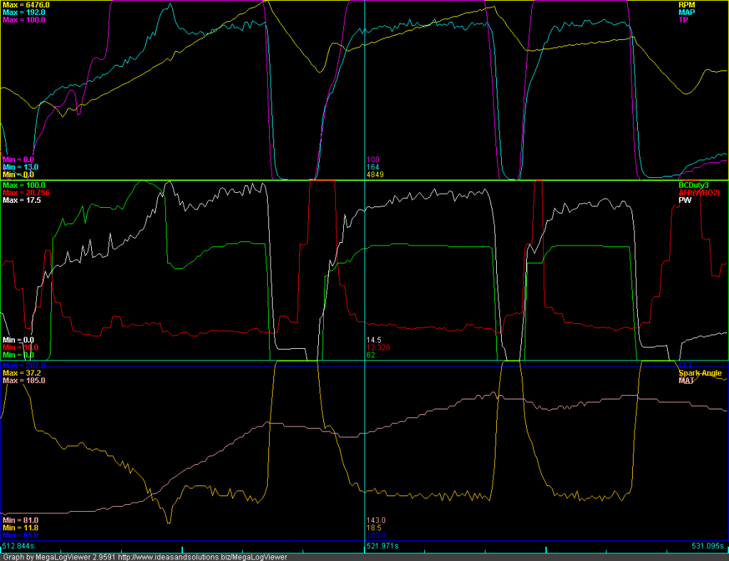
Notice the boost overshoot in second gear. You can also see that the boost control solenoid duty cycle goes to near 100% and then suddenly drops down when this happens (logged as "BCDuty3").
So, I dug into the code and found that the MS-1 uses an Integral+Derivative control loop for CLEBC. There is no proportional term at all. The algorithm is:
Duty Cycle(new) = Duty Cycle(old) + "Proportional Gain" x ( kPa Target - kPa ) - "Differential Gain" x ( kPa(current) - kPa(previous) )
if Duty Cycle(new) > 100% then Duty Cycle(new) = 100%
if Duty Cycle(new) < 0% then Duty Cycle(new) = 0%
What this means is that the algorithm is prone to integral windup, and it is up to us to ensure that integral windup doesn't happen.
Integral Windup:
I know what you're thinking. "OK, Mr. Smarty Pants, what the heck is 'integral windup'?"
Well, I'm older than most of you. In fact, I'm nearly as old as Curly! Contributing to my advanced age are two daughters, one who is grown and married and almost completely returned by the aliens, and another who has recently been taken by those same aliens (she's 15). In my mind, the best way to explain integral windup is with an analogy to a teenage daughter. Here's an example of the daily fight between my wife and my teenage daughter:
Wife: "Clean your room" or "Do your homework" or "Get off the computer" or (fill in the blank).
Daughter: (Assuming she responds at all) "Yeah, whatever . . ."
Wife (more loudly): "Clean your room" or "Do your homework" or "Get off the computer" or (fill in the blank).
Daughter: (Same response)
Wife (even more loudly): "Clean your room" or "Do your homework" or "Get off the computer" or (fill in the blank).
Daughter: (Same response)
. . . and so on.
In the end, my poor wife has made continuous control inputs into a system (a teenage daughter) that is fundamentally not controllable. The desired system response is not achieved. However, my wife gets totally wound up and pissed off -- which then affects my life negatively. This, my friends, is integral windup.
What does the above have to do with CLEBC? Plenty. There are regions where boost does not (cannot) respond to EBC valve duty cycle changes. If we are in one of these regions and attempt to perform CLEBC with an integral+derivative algorithm, the only thing that will happen is that the EBC valve duty cycle will get wound up and pissed off -- it will rise to 100% or fall to 0% (thankfully, it is limited to these values). Despite this, the target boost will not be achieved. And, once we get into a region where the system is responsive, the CLEBC algorithm will have a lousy starting point and a much more difficult problem to solve -- leading to boost overshoots and undershoots.
There are two regions where this happens:
1. When the throttle isn't open. Megasquirt uses MAP as an indication of boost. MAP, by definition, is sourced AFTER the throttle. As we all know, the throttle is the primary and most powerful control for MAP. If you are trying to control boost (i.e., MAP) with EBC valve duty cycle and the throttle is closed or partially closed, you are wasting your time.
2. Before the turbo spools up. If the engine isn't in an RPM region where the turbo can generate boost, you can be at 100% EBC valve duty cycle all day long and boost won't rise at all.
So, How Can We Use CLEBC and Avoid Integral Windup?
Elementary. Use a hybrid of OLEBC and CLEBC. CLEBC is used in the regions where boost (i.e., MAP) is responsive to EBC valve duty cycle. OLEBC is used everywhere else. This is why it is critical that OLEBC be tuned first.
Looking at the EBC controls, there is a parameter called "Closed Loop kPa Limit (kPa)."
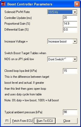
This parameter is intended to be a safety that forces use of OLEBC when it is apparent that CLEBC is not working. It does this by comparing currently sensed boost to the target boost in the "Boost kPa Target" table. A side effect of this parameter is that, if we are clever with our "Boost kPa Target" table, we can actually control the regions where OLEBC and CLEBC are used.
Here's an example (this is what I'm currently using, BTW):
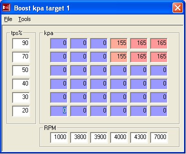
As you can see, I've entered a target of "0" in the areas where I want to use OLEBC, namely at small throttle settings and at low RPMs. Since "0" will naturally fall outside of the "Closed Loop kPa Limit (kPa)", I am forcing OLEBC in those areas. The idea is for OLEBC to handle these transient/uncontrollable regions and to give CLEBC a decent starting point at the handoff.
A few implementation details:
1. Determine the minimum RPM for using CLEBC by using the data collected during OLEBC tuning. Basically, with OLEBC set to 100%DC, the lowest RPM where target boost is achieved will be the minimum RPM for CLEBC.
2. Minimum TPS% is set based upon a knowledge of the flow characteristics of butterfly valves (the throttle is such a valve). Basically, by the time you're at 70% throttle, the effect of EBC valve duty cycle will be evident on MAP (assuming you are in the RPM range for boost).
3. The handoff point from OLEBC will vary depending upon external conditions. Because of this, you want to set the "Closed Loop kPa Limit (kPa)" to a value that accounts for OLEBC variability. Currently, I'm using 30kPa for this value and it has been working for the temperature extremes I've seen.
4. When setting the "Proportional Gain" and "Differential Gain" values, it helps to plot EBC valve duty cycle. In my installation, this is the "BCDuty3" parameter. What you are shooting for is a curve that expeditiously achieves your boost target without a lot of overshoot or oscillations. I'm currently using a "Proportional Gain" of 20 and a "Differential Gain" of 0.
Here are some sample plots:
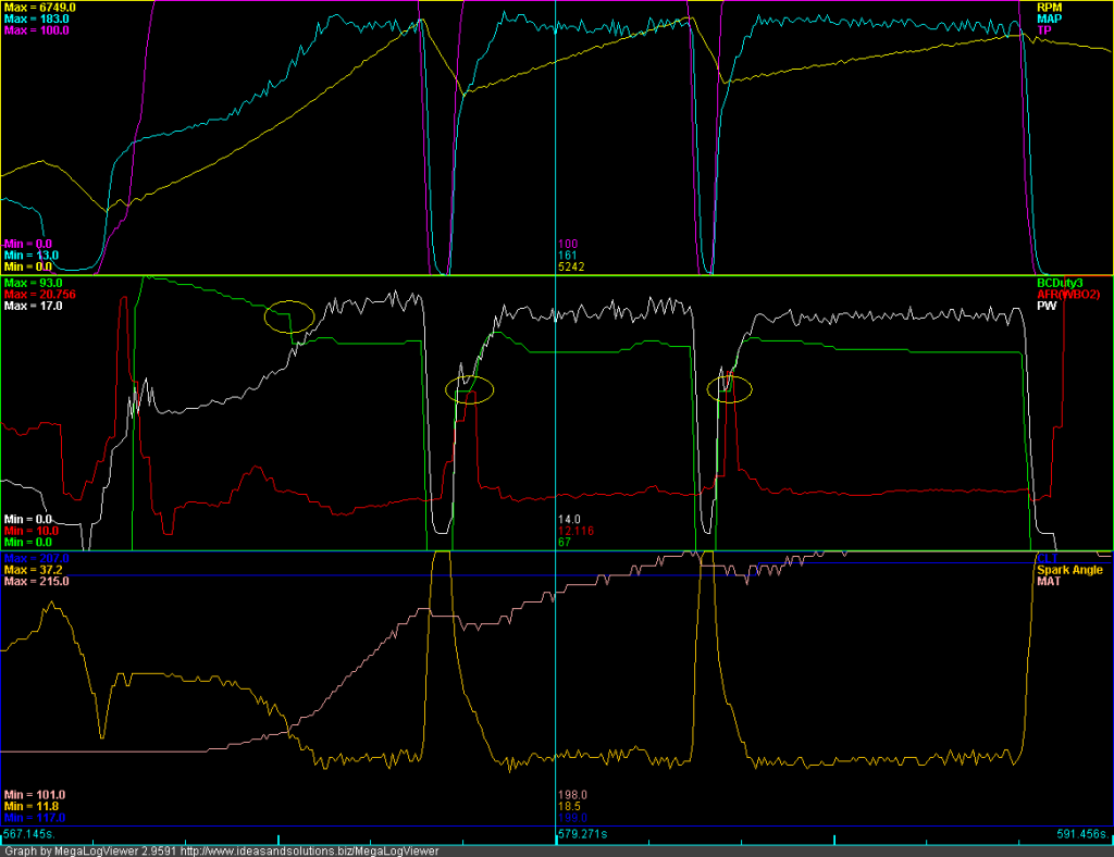
This plot was made on September 13 in some pretty hot conditions (notice minimum MAT is 101 and maximum MAT is 215). I circled the OLEBC to CLEBC handoff points in yellow. You can see that after handoff, the CLEBC seeks its target dynamically. On this particular day, CLEBC was settling to 67%DC.
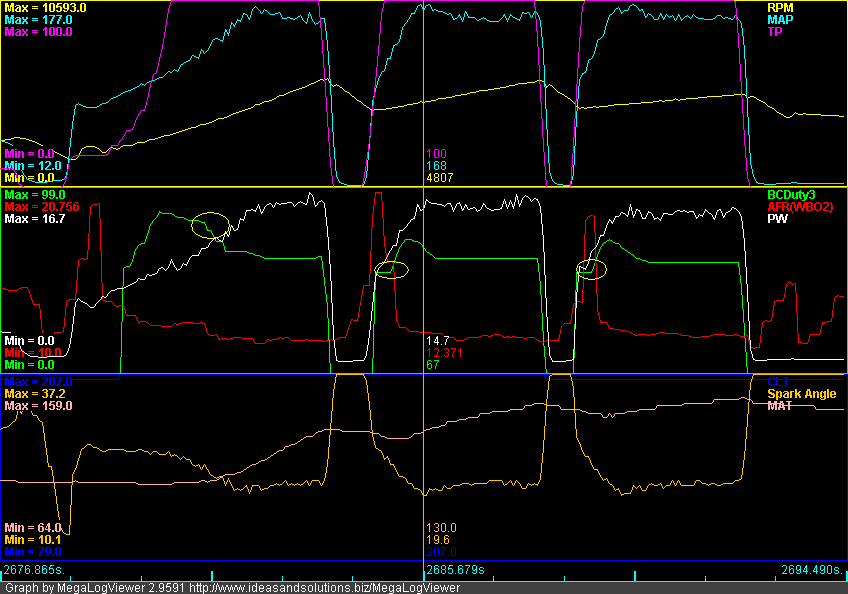
This plot was made yesterday evening in cool conditions (notice minimum MAT is 64 and maximum MAT is 159). Again, the ODEBC to CLEBC handoff points are circled in yellow. On this particular day, CLEBC was settling to 59%DC. This makes sense. In cooler conditions, it takes less DC to achieve a boost target.
Cross-posting to my build thread. YMMV.
By the end of that thread, I had finally figured out (with the help of some code inspection) Closed-Loop EBC on my MSPNP9093. I've been meaning to post the details, but got sidetracked by life. The delay has confirmed that, when tuned properly, the MS-1 CLEBC works consistently and is not affected by temperature. I've been operating it since early September without any changes. So far in North Texas, I've seen well North of 100 and well South of 30. The algorithm just works, it goes to and holds my target day in and day out. So, without further ado ...:
Prerequisites:
Before tackling CLEBC, it is assumed that you've setup and tuned Open Loop EBC. See the earlier thread for details on this. A well setup OLEBC is critical to getting your CLEBC working correctly. In addition, some of the data that was used to setup OLEBC will be re-used for CLEBC.
The other thing that is needed to successfully use CLEBC is a throttle position sensor. Make sure to get one installed and working before attempting this.
The Revelation:
I "sort of" got CLEBC working just by playing around with the "Proportional Gain" and "Differential Gain" values. However, when starting from low RPM's, I typically got boost overshoots -- which didn't make any sense for a true Proportional control algorithm. This was a typical pattern:

Notice the boost overshoot in second gear. You can also see that the boost control solenoid duty cycle goes to near 100% and then suddenly drops down when this happens (logged as "BCDuty3").
So, I dug into the code and found that the MS-1 uses an Integral+Derivative control loop for CLEBC. There is no proportional term at all. The algorithm is:
Duty Cycle(new) = Duty Cycle(old) + "Proportional Gain" x ( kPa Target - kPa ) - "Differential Gain" x ( kPa(current) - kPa(previous) )
if Duty Cycle(new) > 100% then Duty Cycle(new) = 100%
if Duty Cycle(new) < 0% then Duty Cycle(new) = 0%
What this means is that the algorithm is prone to integral windup, and it is up to us to ensure that integral windup doesn't happen.
Integral Windup:
I know what you're thinking. "OK, Mr. Smarty Pants, what the heck is 'integral windup'?"
Well, I'm older than most of you. In fact, I'm nearly as old as Curly! Contributing to my advanced age are two daughters, one who is grown and married and almost completely returned by the aliens, and another who has recently been taken by those same aliens (she's 15). In my mind, the best way to explain integral windup is with an analogy to a teenage daughter. Here's an example of the daily fight between my wife and my teenage daughter:
Wife: "Clean your room" or "Do your homework" or "Get off the computer" or (fill in the blank).
Daughter: (Assuming she responds at all) "Yeah, whatever . . ."
Wife (more loudly): "Clean your room" or "Do your homework" or "Get off the computer" or (fill in the blank).
Daughter: (Same response)
Wife (even more loudly): "Clean your room" or "Do your homework" or "Get off the computer" or (fill in the blank).
Daughter: (Same response)
. . . and so on.
In the end, my poor wife has made continuous control inputs into a system (a teenage daughter) that is fundamentally not controllable. The desired system response is not achieved. However, my wife gets totally wound up and pissed off -- which then affects my life negatively. This, my friends, is integral windup.
What does the above have to do with CLEBC? Plenty. There are regions where boost does not (cannot) respond to EBC valve duty cycle changes. If we are in one of these regions and attempt to perform CLEBC with an integral+derivative algorithm, the only thing that will happen is that the EBC valve duty cycle will get wound up and pissed off -- it will rise to 100% or fall to 0% (thankfully, it is limited to these values). Despite this, the target boost will not be achieved. And, once we get into a region where the system is responsive, the CLEBC algorithm will have a lousy starting point and a much more difficult problem to solve -- leading to boost overshoots and undershoots.
There are two regions where this happens:
1. When the throttle isn't open. Megasquirt uses MAP as an indication of boost. MAP, by definition, is sourced AFTER the throttle. As we all know, the throttle is the primary and most powerful control for MAP. If you are trying to control boost (i.e., MAP) with EBC valve duty cycle and the throttle is closed or partially closed, you are wasting your time.
2. Before the turbo spools up. If the engine isn't in an RPM region where the turbo can generate boost, you can be at 100% EBC valve duty cycle all day long and boost won't rise at all.
So, How Can We Use CLEBC and Avoid Integral Windup?
Elementary. Use a hybrid of OLEBC and CLEBC. CLEBC is used in the regions where boost (i.e., MAP) is responsive to EBC valve duty cycle. OLEBC is used everywhere else. This is why it is critical that OLEBC be tuned first.
Looking at the EBC controls, there is a parameter called "Closed Loop kPa Limit (kPa)."

This parameter is intended to be a safety that forces use of OLEBC when it is apparent that CLEBC is not working. It does this by comparing currently sensed boost to the target boost in the "Boost kPa Target" table. A side effect of this parameter is that, if we are clever with our "Boost kPa Target" table, we can actually control the regions where OLEBC and CLEBC are used.
Here's an example (this is what I'm currently using, BTW):

As you can see, I've entered a target of "0" in the areas where I want to use OLEBC, namely at small throttle settings and at low RPMs. Since "0" will naturally fall outside of the "Closed Loop kPa Limit (kPa)", I am forcing OLEBC in those areas. The idea is for OLEBC to handle these transient/uncontrollable regions and to give CLEBC a decent starting point at the handoff.
A few implementation details:
1. Determine the minimum RPM for using CLEBC by using the data collected during OLEBC tuning. Basically, with OLEBC set to 100%DC, the lowest RPM where target boost is achieved will be the minimum RPM for CLEBC.
2. Minimum TPS% is set based upon a knowledge of the flow characteristics of butterfly valves (the throttle is such a valve). Basically, by the time you're at 70% throttle, the effect of EBC valve duty cycle will be evident on MAP (assuming you are in the RPM range for boost).
3. The handoff point from OLEBC will vary depending upon external conditions. Because of this, you want to set the "Closed Loop kPa Limit (kPa)" to a value that accounts for OLEBC variability. Currently, I'm using 30kPa for this value and it has been working for the temperature extremes I've seen.
4. When setting the "Proportional Gain" and "Differential Gain" values, it helps to plot EBC valve duty cycle. In my installation, this is the "BCDuty3" parameter. What you are shooting for is a curve that expeditiously achieves your boost target without a lot of overshoot or oscillations. I'm currently using a "Proportional Gain" of 20 and a "Differential Gain" of 0.
Here are some sample plots:

This plot was made on September 13 in some pretty hot conditions (notice minimum MAT is 101 and maximum MAT is 215). I circled the OLEBC to CLEBC handoff points in yellow. You can see that after handoff, the CLEBC seeks its target dynamically. On this particular day, CLEBC was settling to 67%DC.

This plot was made yesterday evening in cool conditions (notice minimum MAT is 64 and maximum MAT is 159). Again, the ODEBC to CLEBC handoff points are circled in yellow. On this particular day, CLEBC was settling to 59%DC. This makes sense. In cooler conditions, it takes less DC to achieve a boost target.
Cross-posting to my build thread. YMMV.
#6
Thread Starter
Elite Member
iTrader: (4)
Joined: Mar 2008
Posts: 6,301
Total Cats: 696
From: Granbury, TX
OK, information combined and condensed here:
https://www.miataturbo.net/megasquirt-18/how-ms-1-mspnp-ebc-62711/
https://www.miataturbo.net/megasquirt-18/how-ms-1-mspnp-ebc-62711/
Thread
Thread Starter
Forum
Replies
Last Post


