
EBC not opening
 05-19-2013, 08:44 PM
#1
Junior Member
Thread Starter

Join Date: Sep 2011
Location: Chesterfield, VA
Posts: 252
Total Cats: 2
I installed DIYAutoTune.com EBC ( EBC Electronic Boost Control Solenoid Kit DIYAutoTune.com ) today. I connected it to the MS as I said in this post - https://www.miataturbo.net/megasquir...-pinout-72841/ following these instructions ( MegaSquirtPNP by DIYAutoTune.com ).
I have the entire boost duty table set to zero and I am hitting over 180 kpa until over boost kicks in. Without the EBC I was maxing out around 160ish before the actuator opened.
Attached is my tune and log.
I have the entire boost duty table set to zero and I am hitting over 180 kpa until over boost kicks in. Without the EBC I was maxing out around 160ish before the actuator opened.
Attached is my tune and log.
Last edited by travisb; 05-20-2013 at 05:28 AM.

Reply
 0
0

0
 05-20-2013, 12:56 PM
#4
Junior Member
Thread Starter
Join Date: Sep 2011
Location: Chesterfield, VA
Posts: 252
Total Cats: 2
I have MSPNP MS1 running MSnS-extra 029q. I believe the back of the MS case has a label that says version 1.37.
The hoses are connected like the diagram attached below.
And it is wired to Pin 9 on the center 16-pin connector also shown below.
The hoses are connected like the diagram attached below.
And it is wired to Pin 9 on the center 16-pin connector also shown below.
Reply
0
0
05-20-2013, 02:46 PM
#5
Junior Member
Thread Starter
Join Date: Sep 2011
Location: Chesterfield, VA
Posts: 252
Total Cats: 2
I am wondering if I am using the correct pin. I used the wire indicated to be number 9 on the CONNECTOR.
However, on the MS site the pins on the BOARD are described as having pin 1 on the top left and pin 16 on the bottom right. So, I potentially have connected wire #9 to pin #16 if I understand this correctly.
MegaSquirtPNP by DIYAutoTune.com
However, on the MS site the pins on the BOARD are described as having pin 1 on the top left and pin 16 on the bottom right. So, I potentially have connected wire #9 to pin #16 if I understand this correctly.
The top pins are numbered 1 through 8, left to right, and the bottom pins are numbered 9 through 16. Here are the pins� uses:
Pin Number Connection
1 through 8 Breakout header
9 Electronic boost control
10 Alternate O2 Sensor Input (for wideband o2)
11 Input for KnockSenseMS knock box
12 Launch Control Input
13 Clutch Switch connection for launch control
14 through 16 Not Used
Pin Number Connection
1 through 8 Breakout header
9 Electronic boost control
10 Alternate O2 Sensor Input (for wideband o2)
11 Input for KnockSenseMS knock box
12 Launch Control Input
13 Clutch Switch connection for launch control
14 through 16 Not Used
Reply
0
0
05-20-2013, 03:23 PM
#7
Junior Member
Thread Starter
Join Date: Sep 2011
Location: Chesterfield, VA
Posts: 252
Total Cats: 2
Which "ports" are you referring to? The pins and wires or the ports on the sides of the ebc? I am using the correct ports on the ebc according to the diagram in post #4.
The diyautotune site says
One wire connects to a 12 volt source, the other to the Megasquirt, the valve wiring is not polarized so it does not matter which wire you run to 12v+ and which to switched ground at the EMS.
Reply
0
0
05-20-2013, 06:43 PM
#9
Junior Member
Thread Starter
Join Date: Sep 2011
Location: Chesterfield, VA
Posts: 252
Total Cats: 2
I'm not sure why I could not get air through the ebc on the first try. I tried a couple more times and had no problem when the car was off.
I was also able to move air through while the car was running.
I moved the barb to the other port, port 1 on the attached image. In port 1 I could not move air.
I put it back in port 3.
----
Next, I moved the wire to pin 9 on the center connector on the MS (wire 16 on the connector).
----
I took a test drive and attached the trimmed log and tune.
On the first part of my test, around 436 seconds, I set the boost duty to zero in all cells.
Then I set all BD cells to 100 and did another pull at 520 seconds.
In both cases the EBC appeared to not be working and I hit 184 kpa before over boost kicked in.
Reply
0
0
05-20-2013, 07:24 PM
#10
Suggest you slow it down and take one step at a time:
Steps:
1. Confirm solenoid plumbing by blowing through solenoid with power off.
2. Confirm solenoid action by applying ground to the Pin 9 wire (opposite the 12VDC wire). Listen for click. When energized, confirm you can't blow through. De-energize, listen for click and confirm you can blow through.
3. Confirm solenoid action as controlled by MS. In "Boost Control" dialogue, set "0" in "Closed Loop kPa Limit" to force open loop control. In "Boost Duty Targets" dialogue, fill all cells with 100. Turn ignition swith to "ON" and listen for click. When energized, confirm you can't blow through. Now fill all cells with 0. Listen for click and confirm you can blow through.
Once you get past all the above steps, you can start the car and begin tuning. If any of the tests fail, you'll need to troubleshoot to find out why.
Reply
0
0
05-20-2013, 10:00 PM
#11
Junior Member
Thread Starter
Join Date: Sep 2011
Location: Chesterfield, VA
Posts: 252
Total Cats: 2
The solenoid is not getting power when I turn the key. Or at least it is not closing. I can still blow through it. Everything else powers up as normal. When I touch the ground wire from the ebc to the wire going to pin 9 there are no noises from the solenoid.
However, something else happens. I have two fans behind the radiator. When I touch the wires at least one of the fans turn on.
My car is pretty empty on the inside and I have removed the dash, a/c, stereo, etc. I still have the heater and cigarette lighter.
The hot wire is green/black from somewhere near the center of the dash that I tested to be 12v switched.
Is there a more preferred place to wire it in? Also, if it was staying open, then I should not be boosting high like I am...
Reply
0
0
05-20-2013, 10:45 PM
#12
Touch the ground wire from the EBC solenoid to ground for the first test. If we can at least establish that the Green/Black wire is a good source for power, that would be good. Note that there are a lot of wires in the wiring diagram with that color, and I haven't found one yet that would be a clean power source.
Testing with a voltmeter doesn't establish this. For example, if a relay isn't active, you'll read 12V on both sides of the coil even if you are touching the side that goes to ground when the relay activates.
Do you have a wiring diagram?
Testing with a voltmeter doesn't establish this. For example, if a relay isn't active, you'll read 12V on both sides of the coil even if you are touching the side that goes to ground when the relay activates.
Do you have a wiring diagram?
Reply
0
0
05-20-2013, 11:52 PM
#13
Junior Member
Thread Starter
Join Date: Sep 2011
Location: Chesterfield, VA
Posts: 252
Total Cats: 2
I'll have to wait until tomorrow afternoon for more testing.
Here are the wiring diagrams. Thanks again!
Engine control: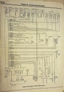 Engine gauges:
 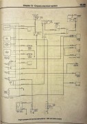 headlights:
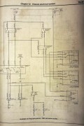
heating, ac, part 1: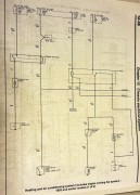 heating, ac, part 2:
 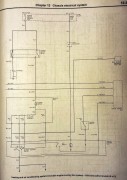 exterior lights:
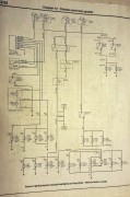
interior lights: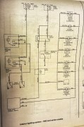 starting:
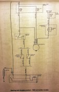
Here are the wiring diagrams. Thanks again!
Engine control:
Engine gauges: headlights: heating, ac, part 1:
heating, ac, part 2: exterior lights: interior lights:
starting:
Reply
0
0
05-21-2013, 09:55 AM
#15
Junior Member
Thread Starter
Join Date: Sep 2011
Location: Chesterfield, VA
Posts: 252
Total Cats: 2
I have not figured out exactly which wire it is in the diagram. I took a couple pictures though.
There is a pair of wires, green/black and green/red that were bundled together. They have silver markings every few inches. I am using the green/black.
They are part of a larger bundle going from the left side to trhe right to the heater.
EDIT:
The green in the green/black is lighter green than in the green/red. There is a LT GRN/BLK -> THERMO-SWITCH -> GRN/RED -> A/C SWITCH in the bottom-right corner of heating, ac, part 2: http://www.imagebam.com/image/66843e255567548
I did remove the A/C.
Reply
0
0
05-21-2013, 10:32 AM
#16
OK. That wire is a signal wire for the ECU. Basically, when the thermoswitch is open (or, in your case, removed), it "seems" to have 12VDC because of current leakage from a pull-up resistor in the ECU. However, there is no power available there. There is no way that there is enough power there to activate a solenoid and trying to do so would introduce massive noise into the ECU.
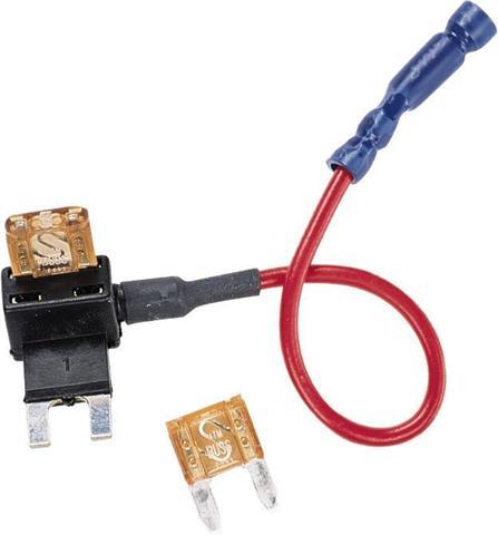
So, let's step all the way back and rewire the solenoid. Source a wire or pull a new wire that you KNOW goes directly to an appropriately sized fuse. In my build, I added a fuse tap into my fuse block and pulled a new wire to supply power for my WI pump and the EBC solenoid. The other end of the solenoid went to Pin 9 of the MSPNP center connector as identified in the picture of the MSPNP directions.
This is a fuse tap (pick it up at your local parts store):
Reply
0
0
05-21-2013, 10:51 AM
#17
I admit that I skimmed the thread thus far so I may have missed this but is your table set to inverted controls like most everyone's? This would mean all 0's would keep the ebc closed and run ALLOFIT. All 100's would run wastegate only. I had this problem when I hooked mine up. I put everything to 100 and wondered why it was not working.
Reply
0
0
05-21-2013, 11:37 AM
#18
I admit that I skimmed the thread thus far so I may have missed this but is your table set to inverted controls like most everyone's? This would mean all 0's would keep the ebc closed and run ALLOFIT. All 100's would run wastegate only. I had this problem when I hooked mine up. I put everything to 100 and wondered why it was not working.
We need to take it one step at a time. Grabbing a proper source of 12VDC for the solenoid is step 1.
If OP follows the troubleshooting/checkout steps given above, it will quickly reveal what the setup is before he even starts the car. We can address this subject at that time. Note that the MSPNP default is 0% for wastegate only.
Reply
0
0
05-21-2013, 02:36 PM
#20
If there isn't anything written on the solenoid, then I would energize it with a battery and measure the steady-state amperage draw. Multiply that by 5 to account for inrush current. I'm guessing a 1-amp fuse will be plenty for this part (I used a 10-amp fuse on my setup where it is in parallel with the WI pump).
As for wire gauge, 18AWG should be plenty.
As for wire gauge, 18AWG should be plenty.
Reply
0
0


