
DIYPNP install: inital tuning
 03-11-2011, 10:51 PM
#1
Junior Member
Thread Starter

Join Date: Jun 2007
Posts: 411
Total Cats: 0
1996 1.6L "Euro" spec. Sequential injection. Supercharged intercooled. LC-1.
Stock injectors. The car started and ran properly with the stock ECU prior to the DIYPNP install.
Just installed a Brain-DIYPNP, with the sequential injection mod. All wiring and vacuum hoses double checked. FP-GND jumped at diagnostic connector, AFM removed & wires done. TPS disconnected.
Pulled out MS2 Rel 3.0.3s from the DIYPNP box. Tunerstudio updated to the latest, the project selection options are a bit different, but I think I got em all.
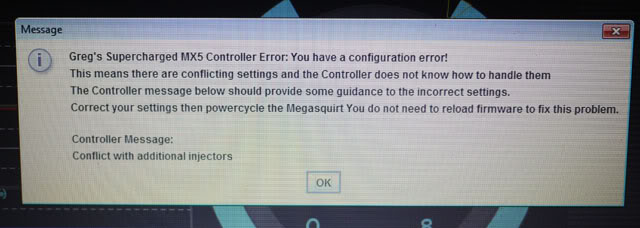
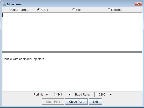
It won't fire up. Power cycling the ECU, I get an error message:
My project settings
Preloaded settings
No spark at the plugs too
HELP
Stock injectors. The car started and ran properly with the stock ECU prior to the DIYPNP install.
Just installed a Brain-DIYPNP, with the sequential injection mod. All wiring and vacuum hoses double checked. FP-GND jumped at diagnostic connector, AFM removed & wires done. TPS disconnected.
Pulled out MS2 Rel 3.0.3s from the DIYPNP box. Tunerstudio updated to the latest, the project selection options are a bit different, but I think I got em all.
It won't fire up. Power cycling the ECU, I get an error message:
My project settings
Preloaded settings
No spark at the plugs too
HELP
Last edited by Greg G; 03-28-2011 at 02:11 AM.

Reply
 0
0

0
03-12-2011, 12:26 AM
#2
Junior Member
Thread Starter
Join Date: Jun 2007
Posts: 411
Total Cats: 0
I found this from another thread..could this be part of the reason? My 1996 Euro spec 1.6 wiring? Brain, could you check with Reverant? 
Well that kinda narrows it down. All the ECUs I built for the EU are for EU-spec cars unless otherwise stated (ie I had a person from Norway that had a US-spec 99).
All EUDM-spec 1.6 NAs have the two CAS signal wires in pins 2F and 2G, where the USDM-spec (and possible the JDM-spec) cars have them in 2E and 2G.
I found out about this the hard way, when I tried to install an MSPNP9093 from DIYAutoTune, in a friend's EU-spec 92, and it wouldn't work at all...so I had to modify his harness to make it work. I removed the 2f pin&wire from the connector and moved it to 2E. Cranked it and it fired right up.
Reply
0
0

 03-12-2011, 04:12 AM
#5
Junior Member
Join Date: Oct 2009
Location: Springfield, MO
Posts: 492
Total Cats: 3
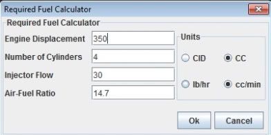
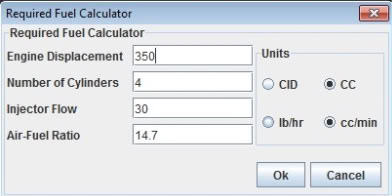
1600cc injector flow on a 1.6L, 4 cylinder at 14.7= 1.7 required fuel
230cc injector flow on a 1.6L, 4 cylinder at 14.7= 11.7 required fuel
Reply
0
0
03-12-2011, 04:19 AM
#6
Junior Member
Thread Starter
Join Date: Jun 2007
Posts: 411
Total Cats: 0
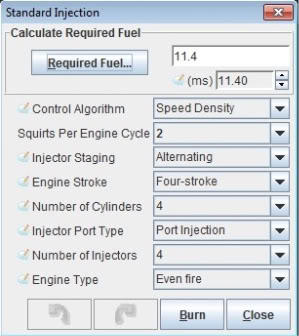
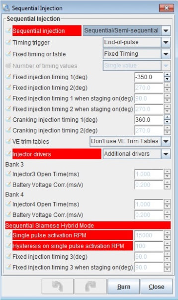
Sorry, I meant I changed engine displacement to 1600 and injector flow to 230cc/min. The numbers on the screen cap were pulled from the ECU, preloaded from Brainy. I'm at a loss as to why I get the "Conflict with additional injectors" error message everytime I power cycle the ECU.
Reply
0
0
03-12-2011, 04:57 AM
#7
Elite Member

iTrader: (10)
Join Date: Jun 2006
Location: Athens, Greece
Posts: 5,990
Total Cats: 361
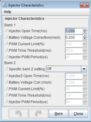
Bank2 specific bank setting should be set to ON.
Do you get a SOLID rpm signal when you crank? It should be above 100rpm and NEVER drop to 0 once it starts reading above 100rpm.
Do you get a SOLID rpm signal when you crank? It should be above 100rpm and NEVER drop to 0 once it starts reading above 100rpm.
Reply
0
0
03-12-2011, 05:11 AM
#8
Junior Member
Thread Starter
Join Date: Jun 2007
Posts: 411
Total Cats: 0
Thanks Reverant!
Aha! Bank 2! Will try that! I assume the settings should be the same as bank 1.
Unfortunately, the shop is closed already :P
Totally new to this, I thought I logged the cranking but when I tried opening it, I got "no data" No I didn't get a solid rpm signal
Looking at the stock ECU/harness, there are wires to BOTH 2E/2F
Oh here's what I get from TS when I cycle it:

Aha! Bank 2! Will try that! I assume the settings should be the same as bank 1.
Unfortunately, the shop is closed already :P
Totally new to this, I thought I logged the cranking but when I tried opening it, I got "no data"
No I didn't get a solid rpm signal Looking at the stock ECU/harness, there are wires to BOTH 2E/2F
Oh here's what I get from TS when I cycle it:
Last edited by Greg G; 03-15-2011 at 06:31 PM.
Reply
0
0
03-12-2011, 05:28 AM
#10
Junior Member
Thread Starter
Join Date: Jun 2007
Posts: 411
Total Cats: 0
This is an MX5 sold here in the Philippines, brought in by Mazda, which I understand is the 1996 90hp Euro model.
Mine is a non-immobilizer model, if that's significant.
Mine is a non-immobilizer model, if that's significant.
Last edited by Greg G; 03-12-2011 at 05:41 AM.
Reply
0
0
03-12-2011, 05:39 AM
#11
Elite Member
iTrader: (10)
Join Date: Jun 2006
Location: Athens, Greece
Posts: 5,990
Total Cats: 361
Two options here: Modify the DIYPNP (recommended) or modify the harness (not recommended).
1) Modify the DIYPNP: There is a wire going for connectorboard 2E to OPTO- on the mainboard. Remove it from 2E and solder it on 2F. Done.
or
2) Modify the harness: Remove the WHITE/BLUE wire from position 2E. Put some tape on it and put it safely out of the way. Remove the WHITE/RED wire from position 2F and put it in position 2E. Done.
Reply
0
0
03-12-2011, 05:49 AM
#12
Junior Member
Thread Starter
Join Date: Jun 2007
Posts: 411
Total Cats: 0
Thanks for the advice.
So the table I posted above is erroneous? What's the white/blue wire in 2E for?
Is this statement of compatibility for the MSPNP in error too? I gave my instructions to Braineack based on this...
https://www.miataturbo.net/mspnp-55/important-compatibility-info-mspnp-94-1-6-a-45600/
So the table I posted above is erroneous? What's the white/blue wire in 2E for?
Is this statement of compatibility for the MSPNP in error too? I gave my instructions to Braineack based on this...
https://www.miataturbo.net/mspnp-55/important-compatibility-info-mspnp-94-1-6-a-45600/
If you drive a 94-97 1.6 Euro Miata and would like to install a MSPNP ECU, please please please order a MM9093 ECU. The Euro 94-97 1.6 Miata wiring harness is very closely related to the 90-93 1.6 cars, and quite different than its contemporary 1.8 counterparts.
If you install a MM9495 or MM9697 ECU into your 94+ 1.6 Miata, you will badly damage the ECU.
Conversely, we have not had any trouble running our MM9093 ECU on these later model Euro 1.6 cars. What we have seen is that non immobilizer equipped 94-97 Miatas are plug and play with the MM9093 ECU, while immobilizer equipped cars need to have 1 wire moved in their harness, as the immobilizer intercepts the fuel pump trigger. (This information shared in good faith and is to the best of our knowledge).
Reply
0
0
03-12-2011, 05:56 AM
#13
Elite Member
iTrader: (10)
Join Date: Jun 2006
Location: Athens, Greece
Posts: 5,990
Total Cats: 361
Having installed an MSPNP9093 on a 90-93 Miata myself, I would say that the instructions are indeed not correct. The problem was not with the fuel pump relay, but with the CAS wire as stated above.
Reply
0
0
03-12-2011, 07:01 PM
#16
Junior Member
Thread Starter
Join Date: Jun 2007
Posts: 411
Total Cats: 0
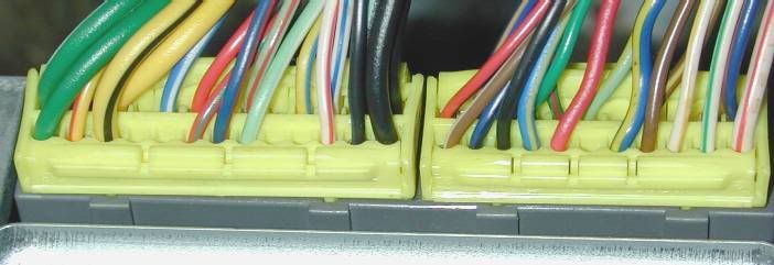
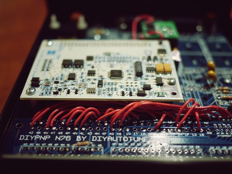
Thanks Rev! It's Sunday and the shop is closed, so I can only read read read, and confuse myself further. Here's a pic of the inside. It's 4E-->4F on the board, correct? But I will probably just do it on the harness, so I can effectively "de-Euro" the wiring and be plug & play with the rest of the world.
Enabled bank 2 in TS. Do I keep this at 2 squirts per cycle, or change to 1?

I do have a 1.6 auto TB with vTPS available. I think I'll get it running without, see that all this is sorted out, before adding something new to the mix. No Euro wiring surprises at the TPS harness, I hope
Enabled bank 2 in TS. Do I keep this at 2 squirts per cycle, or change to 1?
I do have a 1.6 auto TB with vTPS available. I think I'll get it running without, see that all this is sorted out, before adding something new to the mix. No Euro wiring surprises at the TPS harness, I hope
Last edited by Greg G; 03-12-2011 at 10:54 PM.
Reply
0
0
03-14-2011, 01:28 AM
#17
Junior Member
Thread Starter
Join Date: Jun 2007
Posts: 411
Total Cats: 0
Mechanic just called- had him check the continuity of the cas wiring. It goes to 2e and 2g! The wire at 2f is a dead end- goes to a small connector near the ECU, with nothing connected.
Will drop by the shop in while, can anyone please confirm my standard injection settings in the post above? Thanks
Will drop by the shop in while, can anyone please confirm my standard injection settings in the post above? Thanks
Last edited by Greg G; 03-14-2011 at 02:17 AM.
Reply
0
0
03-14-2011, 04:54 AM
#18
Junior Member
Thread Starter
Join Date: Jun 2007
Posts: 411
Total Cats: 0
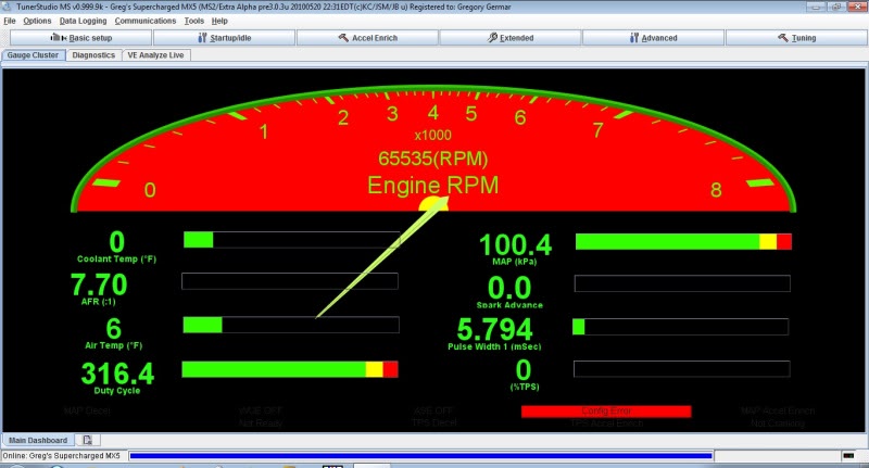
Dammit! Still no start! My rev meter reads 65535 and I still get the "error with additional injectors" message! Fuuuuuuuuuuuuuuuuuuuuu.
What else do you see wrong with the dash? Should the temp be that low?
Ok. Must remain calm. Paging Braineack!!!
Attaching the msq and the msl. The msl shows nothing.
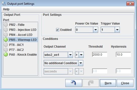
Outputs window (grasping at straws now)...everything ok here?
What else do you see wrong with the dash? Should the temp be that low?
Ok. Must remain calm. Paging Braineack!!!
Attaching the msq and the msl. The msl shows nothing.
Outputs window (grasping at straws now)...everything ok here?
Last edited by Greg G; 03-17-2011 at 10:45 PM.
Reply
0
0
03-14-2011, 08:35 AM
#19
Boost Czar

iTrader: (62)
Join Date: May 2005
Location: Chantilly, VA
Posts: 79,729
Total Cats: 4,126
The 65535RPM shows a conflict error. Did you change anything in the map that was loaded? Warmup LED settings dont look like anything I would have set them to.
I dunno why additional injectors would be turned on, to throw the error.
I dunno why additional injectors would be turned on, to throw the error.
Reply
0
0


