When you click on links to various merchants on this site and make a purchase, this can result in this site earning a commission. Affiliate programs and affiliations include, but are not limited to, the eBay Partner Network.
It's clear as day that everything is working except RPM in my datalog. Data log one no MAF.msl
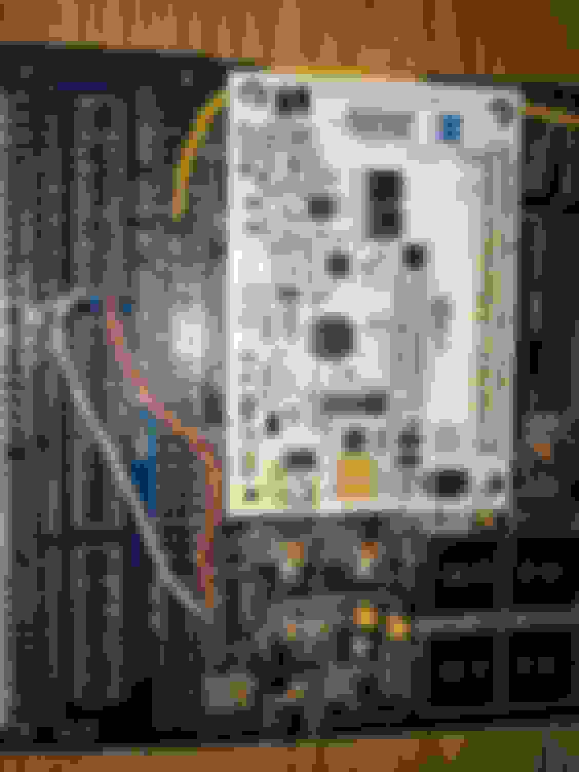
Alright, my rpm isn't syncing, from what I can see I have it wired up correctly. The pull up is on the 12v and I have the wiring across the boards correct. Does anybody see an issue that I don't?
Ok, so there are several things wrong in this wiring that i have found in a few moments of looking at it. You need to completely check over everything with the 94-95 diypnp documentation that DIY has or the stuff on trubokitty.com.
4C and 4D should go to SG not GND
1j/4s should be going to ALD not an out
1L should be going to WLD not where it is now.
Only half of your injectors are hooked up
This is assuming you are wiring for a 94/95. Would be different for 96/97 but yours is still wrong.
Okay, when I was doing injectors I thought you only had to do one not both jumpers.
On DIY autotunes site it says that 4A-4D should all be grounded. It also says 1L should for radiator fans. As well as 1j/4s for AC.
I see on Trubokitt.com it says different. I will make the changes and give an update on everything. Thanks a lot.
Except for the injectors I did the modification to the new specifications. I plugged it in really quick and it said not synced still, idk if I have to have it in the car for it to clear it but I have to go to work so I'll be back on here periodically to check.
you have to have it in the car and attempt to start it before it will say sync. sync is that it is detecting rpm. I am not sure that my recomendations will make in difference for that. The difference between the DIY site and trubokitty is that trubokitty setup is the way Brainiack does it. That is how i have done it and it works well. You will want to do that composite log and upload it.
I figured DIYPNP would have the correct documentation, honestly didn't know it was there lol. But I have everything good to go, and will be installing it today.
their docs are old, and basemaps are on older firmware that dont have the idle up code/wiring...
also, you should go back in and clean up your work so you dont have to troubleshoot later...
example: where it looks like aled and wled are touching from the excess exposed wire...
a lot of those solder joints just like really bad in general, like the SGND on 4D. And if that wire ever touches the 5v hole next to it...
and input 1 out seems to being to both PE1 and PA0...
and youre missing r14...
Yeah I'm going to buy some wire today, I really was just very low and I had to solder new wires around the old so I burnt a few (didn't help I had my iron too hot by accident) I'm going to redo everything today. I thought it would be a lot more work wiring it up. DIYautotune says to leave out R14 for AC. What firmware is the base map on Trubokitty?

 03-11-2017, 10:19 AM


 0
0


