When you click on links to various merchants on this site and make a purchase, this can result in this site earning a commission. Affiliate programs and affiliations include, but are not limited to, the eBay Partner Network.
Looks very good indeed, thanks for sharing the love!
Thanks man!
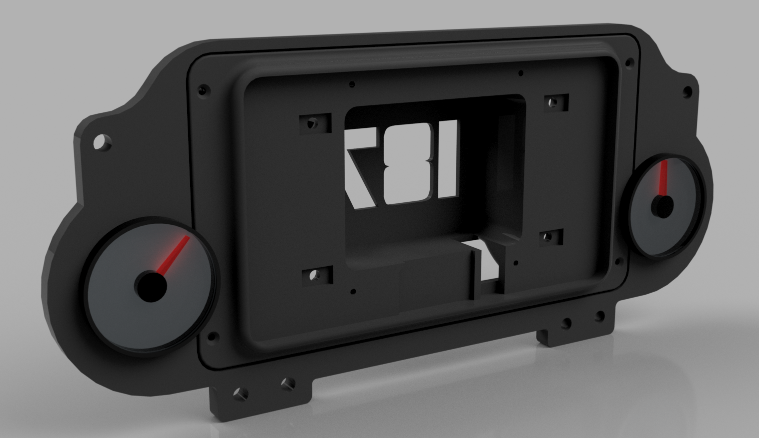
I got feedback from a customer. The cluster was way too wide for the stock cluster hood. I made it a bit more narrow at the expense of making the universal cluster not universal anymore lol..
Hi there! Super interested in the dash. I noticed that the Google Doc's tutorial isn't complete. Do you have one that is finished? Im super interested in making one/getting one.
I need to take better photos of this, but since I have an NA, I took the speedo out of the gauge cluster, tapped into the harness for signal and ziptied it up under the dash. Did the same thing with the fuel gauge, but mounted it in a gauge pod I have under the radio.
I need to take better photos of this, but since I have an NA, I took the speedo out of the gauge cluster, tapped into the harness for signal and ziptied it up under the dash. Did the same thing with the fuel gauge, but mounted it in a gauge pod I have under the radio.
This looks great, Would you be able to chat via DM or something about what you did with the speedo? Looking at doing something like this in my NA
I'll post something up tonight. My phone camera shattered (don't keep your phone in your pocket working in the garage....) otherwise I would have snapped some photos during install.
I look forward to it - I'm hoping to mount the Pi Dash and keep the stock cluster for the time being to record mileage but the main thing I'm trying to understand (before I pull ll the dash off) is how to get the signal from the VSS in the trans to the cluster AND the Pi Dash. My insurer want to know the mileage when renewing my cover mainly - but I also like to try to keep factory functionality when possible in case I change my mind later down the road.
I look forward to it - I'm hoping to mount the Pi Dash and keep the stock cluster for the time being to record mileage but the main thing I'm trying to understand (before I pull ll the dash off) is how to get the signal from the VSS in the trans to the cluster AND the Pi Dash. My insurer want to know the mileage when renewing my cover mainly - but I also like to try to keep factory functionality when possible in case I change my mind later down the road.
NA8 has a signal going from the gauge cluster to the ECU with factory wiring. NA6 gauge cluster has the spot for the signal but no wiring in the chassis to accommodate it. There's a writeup somewhere on this forum on running a wire from the NA6 cluster directly to MS for VSS.
Okay so my setup is a little... janky but it works. I didn't realize that the NB STL is pretty much the same as the NA, so I'll have to re-print my cluster to get the holes for the fuel gauge and oil pressure.
I also didn't print this myself - I don't have a 3D printer and no one I know has a bed large enough to print this. I uploaded the files to 3DHubs and had them print ABS, 60% in-fill, 300um layer height. Cost for all three pieces as around ~200 and shipped rather quickly.
I recommend enabling VSS in MS before pulling the cluster to verify it works - for NA8 it should just be a simple toggle (at least it was with my MS3PnP). For NA6 you'll need to run a wire from your gauge cluster to your ECU.
First step is disassembling your gauge cluster. We'll need to pull out the speedo gauge and fuel level gauge from the cluster. It should be pretty straight forward - pop the clips fastening the cluster cover. Flip the cluster over and locate the screws holding the speedo and fuel level gauge in place - there were about three in total per gauge if I recall - it should be fairly straight forward.
Once you get the gauges out you'll be left with this.
Now if you look at the back of the cluster - it's quite easy to trace what wires feed what sensors. The fuel level sensor has ignition power, ground, and a sense wire. The speedo has ground and a sense wire.
You'll have to match up the wires (F, and A - I sourced power and ground elsewhere from an auxiliary fuse box) on the chassis harness. I chose to pull down the gauge cluster connectors from the gauge cluster area to the foot-well area. You'll need to do this with your speedo cable anyway - I've removed my dash three times over so it may have been a bit easier for me to guide the wires down so YMMV.
Here's what it looks like - I used posi-tap connectors for quick and easy connections to the factor harness.
Now here's where my setup gets a little less than perfect... I just shoved the speedo up under the dash and secured it with a ziptie. It seems secure enough and works - though a more permanent solution would probably be advisable.
For the fuel level sensor - I passed the wire through to my stereo area and hot glued it into my DDM works radio mount. It looks horrible but it works for now - I plan to move it to the pi dash at a later time.
Hopefully this helps - let me know if you have other questions
I found these two posts regarding VSS on the NA6. Mine is a 90, but it's interesting to me that my mechanical speedo actually drives a VSS as well. Very good and useful information. Seems to me like running the speedo wire to the MS eliminates the need for a GPS module for speedo, right?
Seems to me like running the speedo wire to the MS eliminates the need for a GPS module for speedo, right?
For most people, yeah. No need to use GPS module unless you need super accurate high resolution data for track work, or you're swapping a non-Mazda trans.
wow ok this is answering a lot of the questions I had in my head. - thanks to everyone who's helping out
Looks like I'll be mounting the speedo somewhere under the dash with the cable connected as cpierr03 suggested.
It seems like I will need to then run a wire from the RSW to one of these inputs "Datalog In (or tableswitch, cam in, etc)" as suggested in Aidandj's guide here: https://www.miataturbo.net/megasquir...6-miata-82518/
Then it also looks like I will need to add a pullup resistor as per this post: https://www.miataturbo.net/ecus-tuni...-wiring-59814/ since my ECU is a PNP2 and doesn't feature one. Hopefully then it's a case of configuring it in tunerstudio right?
Can anyone confirm if I'm getting this correct or if I need to do anything different?
Has anyone kept their stock fuel and water temp gauges? The latest thingiverse files don't seem to have the cutouts and while I do have sensors for both keeping the analog gauges isn't a bad thing.
Has anyone kept their stock fuel and water temp gauges? The latest thingiverse files don't seem to have the cutouts and while I do have sensors for both keeping the analog gauges isn't a bad thing.
I'm happy to accommodate any changes you might like to the design. Design halted as I sold my Miata. No more printing and running out in the car to test fit unfortunately.
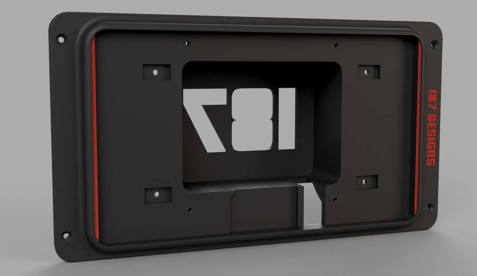
Updated the screen mount with tabs to stop the screen deflecting when touching the sides. Anyone want any cad files etc for the mounting plate etc?
First off, thanks so much for sharing this awesome work! Really looking forward to the PiDash :-)
I would like the CAD files if you still have them though, as the main dash piece is too big for my print bed so I need to split the part into multiple prints. Thanks in advance!


 03-02-2020, 08:52 AM


 1
1


