Did I fry my daughterboard?
#1
So I've been assembling my MS3/MS3X for my 90 miata using Frank's guide. Got pretty far, was able to update the firmware, connect to tuner studio, and flash a map. I then tried to adjust the VR circuits and could NOT get the upper leg of R54 to go lower than 4.9v, and couldn't get the lower leg of R17 above 2.3v... no matter how much I turned the potentiometers (I probably turned them too much). All of this was with the daugterboard plugged in, btw.
Then all of a sudden, after adjusting the pots some more, R54 and R17 read super low, like 200 mV. Checked the 5v out on the voltage regulator/U5 and it was also really low. U5 got super hot, too. Like too hot to touch. I pulled off the daugtherboard, and voila... U5 shot back up to 5v, and the overheating stopped.
What can you guys make of this info? I feel like I must have fried the daughterboard, and I must have ruined the pots as well. Is it bad to adjust them while the megasquirt is powered on?
Thanks a lot for your guys' help, it means a lot.
#2
I'm going with you shorted it somehow from assembly, and it took a while for the short to heat up and break something.
typically when you short the daughterboard it's instantaneous, but the cpu itself typically heats up, not 5 volt regulator.
Makes me think you put a diode/cap in wrong or something.
typically when you short the daughterboard it's instantaneous, but the cpu itself typically heats up, not 5 volt regulator.
Makes me think you put a diode/cap in wrong or something.
#3
<p>
</p><p>Post a high-res picture of the board</p>
So I've been assembling my MS3/MS3X for my 90 miata using Frank's guide. Got pretty far, was able to update the firmware, connect to tuner studio, and flash a map. I then tried to adjust the VR circuits and could NOT get the upper leg of R54 to go lower than 4.9v, and couldn't get the lower leg of R17 above 2.3v... no matter how much I turned the potentiometers (I probably turned them too much). All of this was with the daugterboard plugged in, btw. Then all of a sudden, after adjusting the pots some more, R54 and R17 read super low, like 200 mV. Checked the 5v out on the voltage regulator/U5 and it was also really low. U5 got super hot, too. Like too hot to touch. I pulled off the daugtherboard, and voila... U5 shot back up to 5v, and the overheating stopped. What can you guys make of this info? I feel like I must have fried the daughterboard, and I must have ruined the pots as well. Is it bad to adjust them while the megasquirt is powered on? Thanks a lot for your guys' help, it means a lot.
#4
Joined: Apr 2014
Posts: 18,642
Total Cats: 1,866
From: Beaverton, USA
<p>Did you ever remove those diodes you had?</p><p>I had the same issue of shorting the power supply assembling mine.</p><p>Doubt the daughterboard is fried, other stuff might be though.</p><p>Also post pictures of everything.</p>
#6
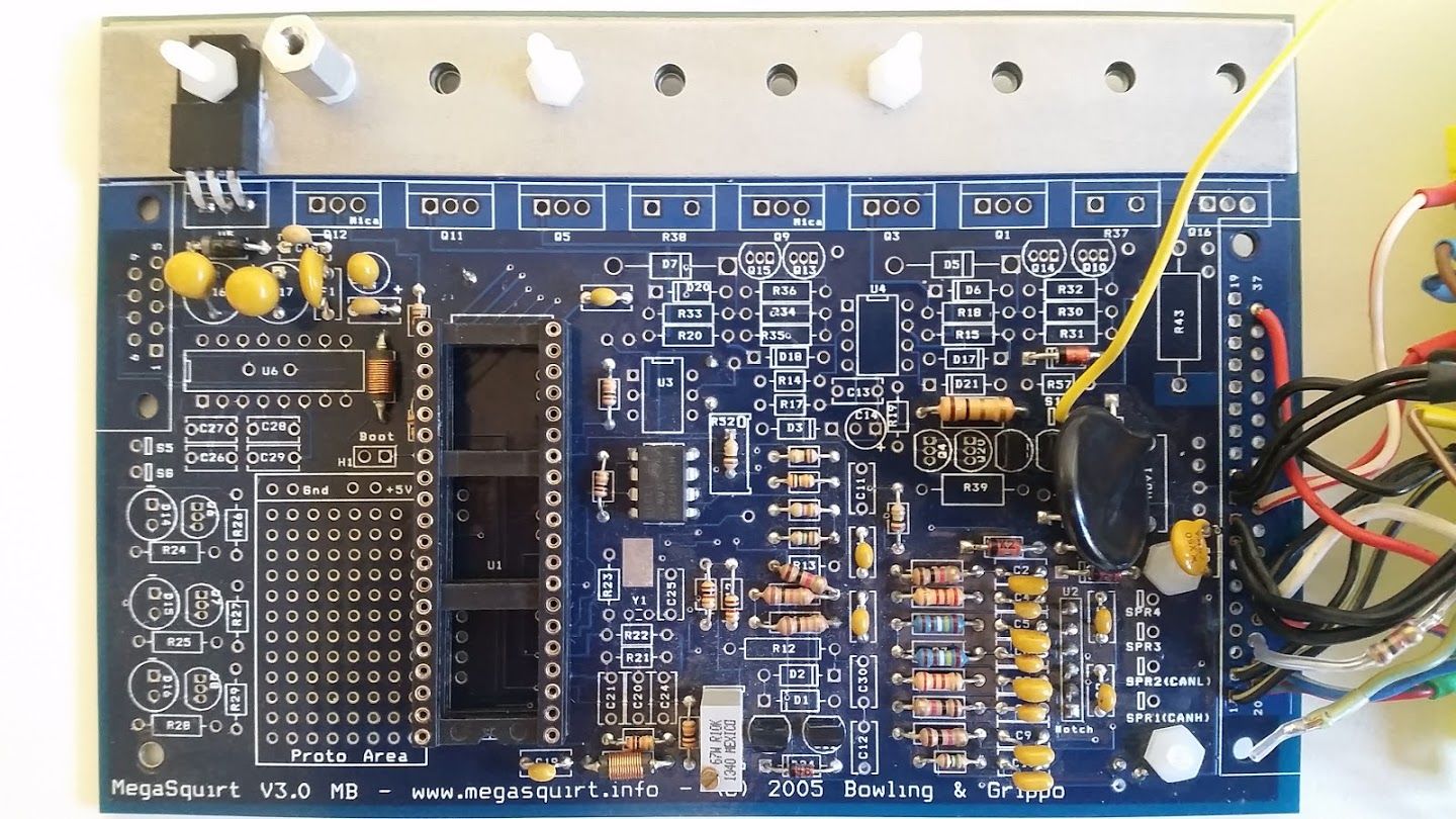
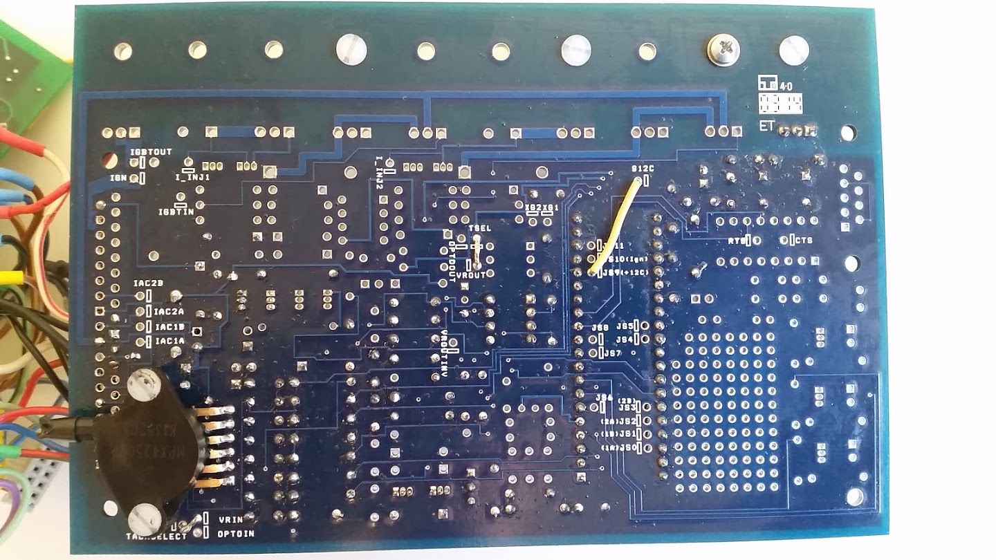
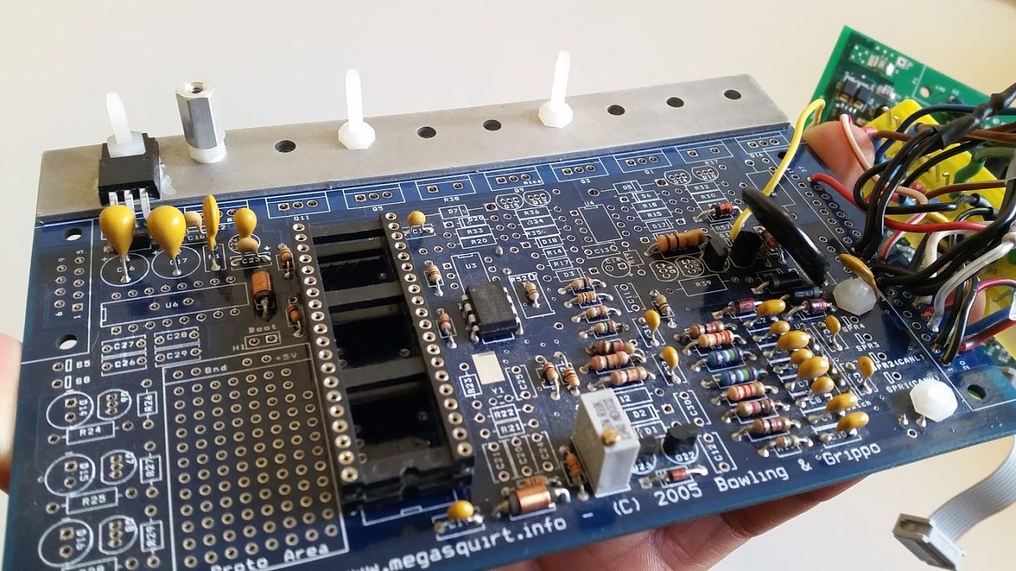
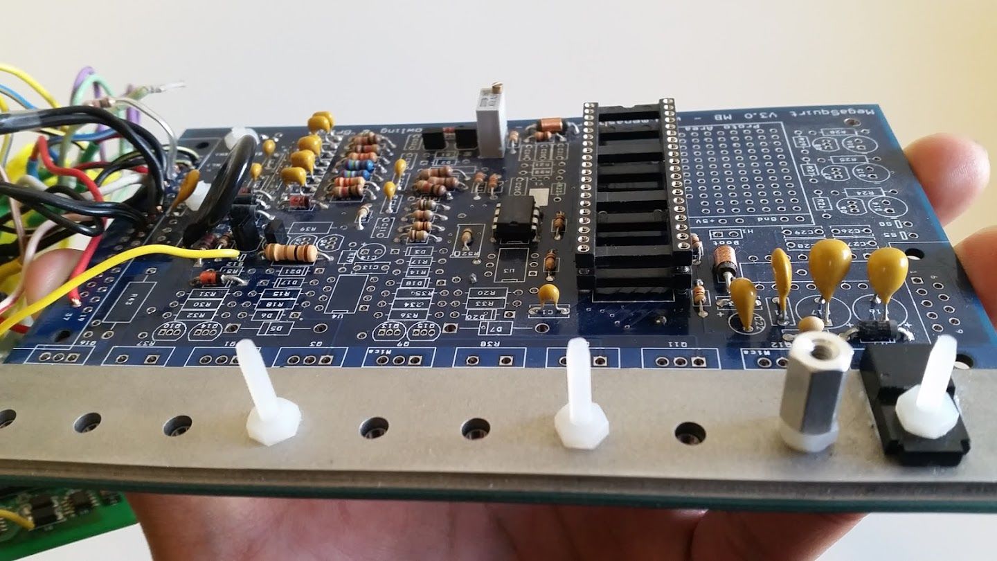
These pictures okay?
Braineack: I double-checked all the diodes on the main board and didn't see anything off. Tried checking the capacitors but it's really hard to discern polarity.
aidandj: I did remove the diodes. Connected S12 on the main board to D1 on the MS3X, just like Braineack said.
As you can see the ECU connecter is already hooked up. So the MS3X is powered along with the MS3. Not sure if that matters but thought it worth mentioning.
#14
Double-checked my harness and I don't see anything wrong. I followed this diagram:
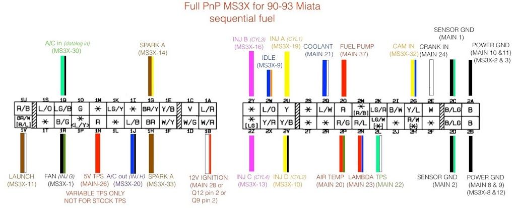
The only difference is, I have a 1k resistor bridging pin 22 with pins 8 & 9 for ground (for the stock TPS). Pin 22 is not connected to the ECU harness at all.
Also I remembered that, when I powered up the megasquirt to adjust the VR circuits, I accidentally hooked up the ground source to one of the sensor ground pins (main pin 1 or 2) instead of the power ground pins (main pins 8-11). Didn't think anything of it since they're both ground. Could this have damaged it?
#17
Pin 22 of the main board. It says in Frank's guide to connect the tps input to ground (for those planning not to use a variable tps), so that's what I did. I actually started a thread a few weeks back for clarification regarding this matter. I plan to run a vtps eventually but I want to make sure it runs well completely stock first.
So I can just unplug the tps instead of running the 1k resistor, huh? And the car will run fine with the tps unplugged? So much simpler.
So I can just unplug the tps instead of running the 1k resistor, huh? And the car will run fine with the tps unplugged? So much simpler.
#19
Turns out the daughterboard WAS fried. Replaced it and it seems fine now. I guess the daughterboard doesn't always heat up when it goes bad.
I still have the problem with the VR circuit on the MS3X board though. Lower leg of R17 maxes out at 2.33 volts. Anyone know how to troubleshoot this?
I still have the problem with the VR circuit on the MS3X board though. Lower leg of R17 maxes out at 2.33 volts. Anyone know how to troubleshoot this?


