When you click on links to various merchants on this site and make a purchase, this can result in this site earning a commission. Affiliate programs and affiliations include, but are not limited to, the eBay Partner Network.
Circuit Smoke Mystery: Can't find anything wrong with my MegaSquirt build?
So I've just finished building my first megasquirt based off the MS3.0 board following the guide on trubokitty.com.
I made the wiring harness and go plug in just the main board on my '97 miata to test all the voltages and such as detailed on msextra testing section: MS3X V3.0 Hardware Manual 1.5
Well, I start getting some smoke over from around the MAP sensor, so I immediately cut the key off.
After a visual inspection, I cant find anything wrong, other than the smell which still appears to come from the MAP sensor.
All of my diodes are orientated correctly. All my caps look fine. My solder joints are good enough.
So I rig up a 12v power supply with a 1A fuse.
Turning on the power supply, everything is fine and the mainboard is drawing 18mA. Again, following the testing guide on msextra I get 12v to regulator and 5v output off the regulator.
There's 5v output as well to the correct 40-pin connector pins.
Then I test the MAP sensor. 5V going into the input, and 1.75v coming off the signal line. I attach a hose to the MAP sensor and blow in it. I can get the voltage to rise to 1.9v before my lungs give out.
This appears to be in line with the datasheet, 100kpa atmospheric pressure should give off above 1.5 according to datasheet here: https://www.nxp.com/docs/en/data-sheet/MPX4250A.pdf
I plugged in the computer and extra board and power it on. Nothing crazy happens.
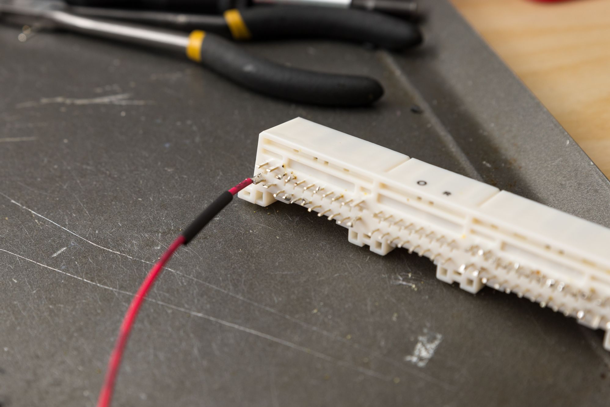
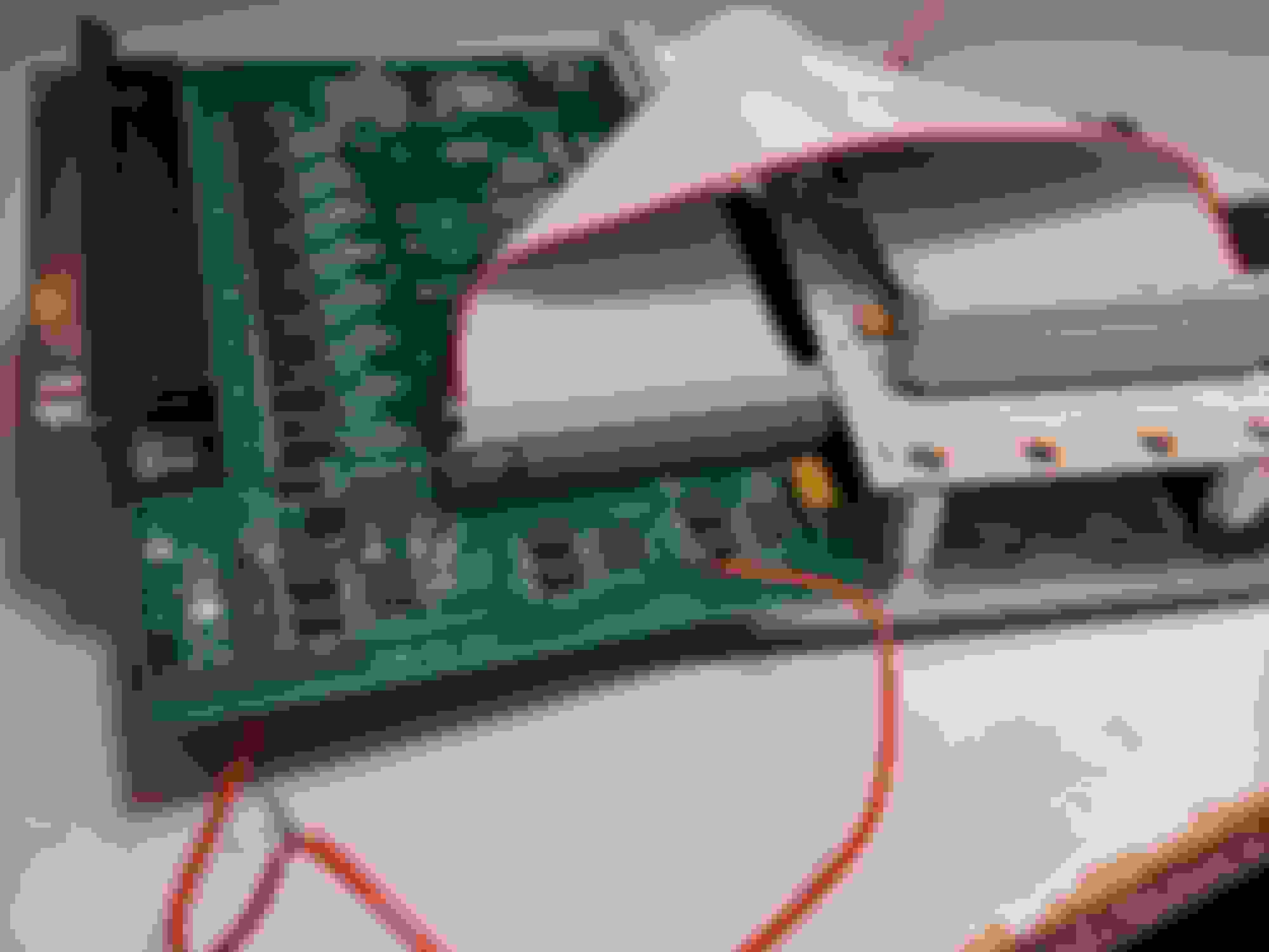
I'm stumped, there was definitely smoke from somewhere. Do I go try to plug it back up to the car? I've attached some pics so maybe one of y'all can visually see something I've missed.
Here's a google link to the photos in case these don't show up.
If it works on the bench, it's probably in the wiring. See if you've got a wire soldered to a pin that's off by 1, especially any grounds / power wires.
I figured the same thing. But I've triple checked my harness, and I had a friend check it. And what about the smoke? The smoke definitely came from something on the board, what should I do about that?
I've also included pics of harness in that google photos link in my first post
more pics of both sides of the board on the other end,please
I have added pictures showing the full board both sides. You'll notice a bit of board burn around the regulator, that is from having to unsolder it once and having a tough time getting it out from it absorbing all the heat.
However, the regulator still functions as it should.
I also realize the LEDs aren't doing anything, but ive just added them to fill in the holes on the cover.
Malic, thanks for the suggestions, but I have checked those and it's just the lighting in the pics.
Well, after several weeks of being busy I was finally able to figure out what was wrong by pulling out the voltmeter. I also realized when looking up other wiring diagrams that the trubokitty is opposite the intuitive way of viewing the connector imo. I drew up a nice pic so you can see my mistake:
See intuitively, I followed the trubo guide by looking at the front of the connector and then wiring it up. Well turns out, his guide is from the back view of the connector, where you're actually doing the wiring. The top picture to me makes more sense.
Now I have to figure out how to remove lots of heat shrink and hot glue and resolder this entire connector fml.
Last question, since testing this I attached 12 volts to sensor ground, what components on the main pcb do you think would have been damaged by this?
It's drawn from looking at it from the side you solder on -- this is much more helpful when building. Plus the sections of each connector are broken out on my diagrams and should have been a clue. Plus my writeup has pictures that starts with the red power wire...
it's also why i leave the OEM color coding in them too -- to make sure youre referencing correctly.
The above diagram you have above must be hella old, cause I replaced most my jpgs with a label on the bottom:
Well unfortunately for me, I didn't follow it that way :/
Anyways, I noticed you don't mention anything about the wideband input. I'm using the AEM x-series wb.
Since I'm running MS3 standalone, can I just cut the narrowband and input the from the aem controller to that pin, IE pin 23, the stock narrowband pin? Or do I use another pin?
And for the sensor ground, can I cut one of the sensor ground wires and dedicate it to the wideband? I don't want to mess up any other sensors that will need the sensor ground wires. So would it be better just to side splice into it and solder it that way?
Or option two, can I use the stock o2 plug and wire from the AEM controller to that?
I know it has two heater connections, the signal wire and the ground. I guess if the heater wires are 12v I could figure out which one is the positive and wire the power and ground to heater wires, then sensor and sensor ground to other two.
Something like:
AEM CONTROLLER ----- MIATA STOCK O2 PLUG
Red(12v switched) --> Black (figure out which one is positive from heater)
Black (Ground) --> Black (figure out which one is ground from heater)
White (signal +) --> Blue (signal)
Brown (signal -) --> White (ground)
I guess I could test this by seeing is white connected to a sensor ground and not a normal ground, and does the heater work like its 12v and a ground.
This is also assuming the narrowband wire on the MS3 can be used for the wideband.
The reason I would prefer this method is so I can easily unplug my whole AEM unit rather than having one plug soldered to my wiring harness.
I'll reply better late, but I usually build wbo2 into ms harness directly and not through any stock wiring.
Can I use pin 23 of the stock narrowband though?
Also just a note about the pics, I'm a 97 Miata and the actual pics of the harness must be an NA6. Although I should of verified the colors of the stock wires, so my mistake.
 04-08-2020, 02:08 AM


 0
0