AC Idle Up Circuit On MS2e Using MS3x Table Switch Input Circuit
 08-11-2016, 10:27 PM
#1
Junior Member
Thread Starter
iTrader: (1)

Join Date: Aug 2014
Location: Wisconsin
Posts: 78
Total Cats: 12
Hi All,
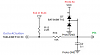
Looking to implement this circuit on the proto area of my MS2e for the Air Conditioning switch input to use the AC idle up code. Brain suggested this in another thread and I just wanted to make sure I was hooking it up correctly w/ both 12v and 5v being involved with a CPU pin. I've got the components in the diagram on the way. I think my main hangup is just knowing what VCC is for a voltage. I'm pretty sure 5v is the answer but just want to be sure. Otherwise, it looks like the input I'm looking for on my 94 is 1Q. Thanks ahead of time.
Looking to implement this circuit on the proto area of my MS2e for the Air Conditioning switch input to use the AC idle up code. Brain suggested this in another thread and I just wanted to make sure I was hooking it up correctly w/ both 12v and 5v being involved with a CPU pin. I've got the components in the diagram on the way. I think my main hangup is just knowing what VCC is for a voltage. I'm pretty sure 5v is the answer but just want to be sure. Otherwise, it looks like the input I'm looking for on my 94 is 1Q. Thanks ahead of time.

Reply
 0
0

0
08-12-2016, 07:08 AM
#2
Boost Czar


iTrader: (62)
Join Date: May 2005
Location: Chantilly, VA
Posts: 79,688
Total Cats: 4,113
diagram markups look good, use s12, not s12c. vvc is 5v.
what input would you use?
what output would you use?
you could build a simpler circuit, but that one will suffice:

doesn't the MS Labs MS2 Enhanced already have a/c idle up?
what input would you use?
what output would you use?
you could build a simpler circuit, but that one will suffice:
doesn't the MS Labs MS2 Enhanced already have a/c idle up?
Reply
0
0
08-12-2016, 07:26 AM
#4
Junior Member
Thread Starter
iTrader: (1)
Join Date: Aug 2014
Location: Wisconsin
Posts: 78
Total Cats: 12
Not exactly sure what the guy in the thread I found had going on, but he said he built that circuit you suggested and it only worked on blower setting 4.
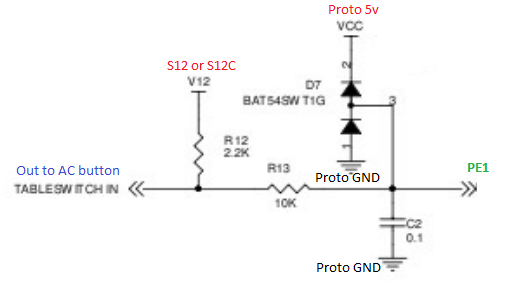
You were thinking it was because the voltage didn't drop far enough and suggested building the ms3x table switch in circuit
You were thinking it was because the voltage didn't drop far enough and suggested building the ms3x table switch in circuit
Reply
0
0
08-12-2016, 08:50 AM
#5
Boost Czar
iTrader: (62)
Join Date: May 2005
Location: Chantilly, VA
Posts: 79,688
Total Cats: 4,113
oh okay. I actually had that issue once, but my car had some weird *** voltage offset problem, using that circuit did help a little, but there was other things going on in my setup.
like i said, either input circuit will work.
like i said, either input circuit will work.
Reply
0
0
03-03-2022, 07:13 PM
#6
Newb

Join Date: Mar 2022
Posts: 3
Total Cats: 0
I tried implementing this circuit but couldn't get it to work. The output was stuck at 5 volts wether or not a/c was on or off, at any blower speed. 2000 Miata, using pin 1P as the A/C input pin.
Measuring the wire directly shows 12v with A/C off, then it goes to 2.5v when A/C is on.
Measuring the wire directly shows 12v with A/C off, then it goes to 2.5v when A/C is on.
Last edited by mazdamx5miata; 03-03-2022 at 07:14 PM. Reason: more context
Reply
0
0

Thread
Thread Starter
Forum
Replies
Last Post


