
94 DIYPNP Build with pictures and questions
 01-17-2010, 10:27 PM
#1
Junior Member
Thread Starter
iTrader: (7)

Join Date: May 2007
Location: Socal
Posts: 332
Total Cats: 0
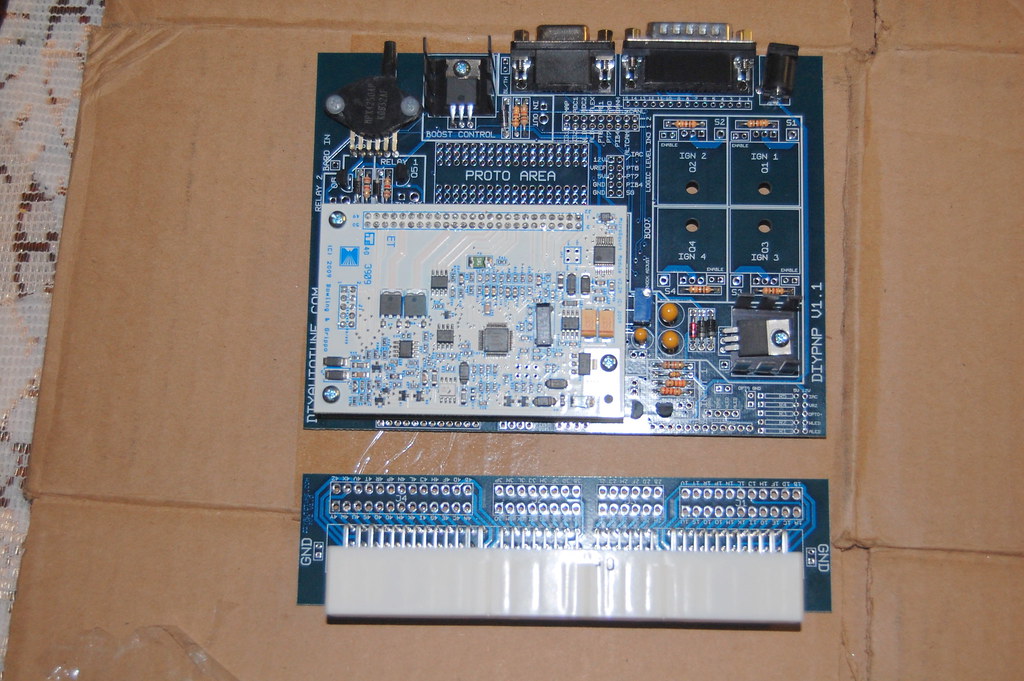
Here's how my DIYPNP looks so far after the basic assembly:
I have some questions based on the instructions.
1)Install all resistors in the locations marked on the board except R26 - the knock sensor trim pot, and R1 through R5. Note that you will have a couple extra resistors reserved for pull-ups. These can be used in the R1 through R5 positions or for certain other mods. - From instructions
I have a couple resisters left over. 5 1k pullups, 5 100 pullups, 3 470 pullups, and 1 ALT CAM 51k. Does that sound about right? I am especially wondering about the ALT CAM resister. I don't know where it goes
2) I also have a IAC FB diode left over. Where is it on the board and is it required?
3) If you are using the high current ignition outputs, add the �ENABLE� jumper next to each output you are using. - From instructions
- How does this apply to me? Does this have to do with the nonexistant Q1-4's?
When using LC1 WB, do you remove the stock o2 sensor or do you have to weld in a new o2 bung? Currently I still have the stock narrowband but I will buy the LC1 when it comes time to install.
I also have the sequential mod kit and GM AIT on the way.
Any tips/hints appreciated. I am trying to read through the mega manual.
Thanks, Long

Reply
 0
0

0
01-18-2010, 01:58 PM
#2
Supporting Vendor

Join Date: Sep 2006
Posts: 2,332
Total Cats: 67
1)Install all resistors in the locations marked on the board except R26 - the knock sensor trim pot, and R1 through R5. Note that you will have a couple extra resistors reserved for pull-ups. These can be used in the R1 through R5 positions or for certain other mods. - From instructions
I have a couple resisters left over. 5 1k pullups, 5 100 pullups, 3 470 pullups, and 1 ALT CAM 51k. Does that sound about right? I am especially wondering about the ALT CAM resister. I don't know where it goes
I have a couple resisters left over. 5 1k pullups, 5 100 pullups, 3 470 pullups, and 1 ALT CAM 51k. Does that sound about right? I am especially wondering about the ALT CAM resister. I don't know where it goes
2) I also have a IAC FB diode left over. Where is it on the board and is it required?
3) If you are using the high current ignition outputs, add the �ENABLE� jumper next to each output you are using. - From instructions
- How does this apply to me? Does this have to do with the nonexistant Q1-4's?
- How does this apply to me? Does this have to do with the nonexistant Q1-4's?
When using LC1 WB, do you remove the stock o2 sensor or do you have to weld in a new o2 bung? Currently I still have the stock narrowband but I will buy the LC1 when it comes time to install.
Reply
0
0
 01-18-2010, 03:28 PM
#4
Junior Member
Thread Starter
iTrader: (7)
Join Date: May 2007
Location: Socal
Posts: 332
Total Cats: 0
So it seems like I don't need any of the pull-up resisters besides the IAC pullup. Will put that in later.
My car is still stock right now (no turbo/SC until summer.) Should I weld an extra o2 bung next to the stock o2 sensor then? How will this integrate into the DIYPNP?
My car is still stock right now (no turbo/SC until summer.) Should I weld an extra o2 bung next to the stock o2 sensor then? How will this integrate into the DIYPNP?
Reply
0
0
01-18-2010, 03:45 PM
#5
So it seems like I don't need any of the pull-up resisters besides the IAC pullup. Will put that in later.
My car is still stock right now (no turbo/SC until summer.) Should I weld an extra o2 bung next to the stock o2 sensor then? How will this integrate into the DIYPNP?
My car is still stock right now (no turbo/SC until summer.) Should I weld an extra o2 bung next to the stock o2 sensor then? How will this integrate into the DIYPNP?
You need to install more pull ups. See here: DIYPNP MegaSquirt installation for the Mazda Miata
Reply
0
0
 01-20-2010, 08:27 AM
#9
Supporting Vendor

iTrader: (33)
Join Date: Jul 2006
Location: atlanta-ish
Posts: 12,659
Total Cats: 134
Needs the flyback diode. I see that it's not listed in the Application Docs for 94-95 and 96-97. However, you do need to install it. Check the main board assembly instructions and scroll down to "assembly notes". You'll see the instructions for R5 for IAC pullup or flyback diode.
Reply
0
0
01-20-2010, 11:43 PM
#10
Needs the flyback diode. I see that it's not listed in the Application Docs for 94-95 and 96-97. However, you do need to install it. Check the main board assembly instructions and scroll down to "assembly notes". You'll see the instructions for R5 for IAC pullup or flyback diode.
Reply
0
0
01-21-2010, 05:14 PM
#11
Damn I dont have any of the in4001's left. I don't want to pay $7 for shipping. Can I use these from radio shack?
1N4001 Micro 1A Diodes - RadioShack.com
1N4001 Micro 1A Diodes - RadioShack.com
Reply
0
0
05-01-2010, 06:30 PM
#14
Junior Member
Thread Starter
iTrader: (7)
Join Date: May 2007
Location: Socal
Posts: 332
Total Cats: 0
So I finished building the DIYPNP for my 94. Two problems:
1) when connected to my computer, the rpm signal is way high. Like 65000 rpms. What's the issue here?
2) When I try to calibrate the tps, I get the same signal with the throttle closed and open. Key is obviously in the "on" position for this step.
My car runs perfect with the stock ecu, so I don't know if the TPS is the culprit or not.
Thanks!
Reply
0
0
05-02-2010, 06:01 PM
#16
Newb

Join Date: Mar 2010
Posts: 1
Total Cats: 0
So I finished building the DIYPNP for my 94. Two problems:
1) when connected to my computer, the rpm signal is way high. Like 65000 rpms. What's the issue here?
2) When I try to calibrate the tps, I get the same signal with the throttle closed and open. Key is obviously in the "on" position for this step.
My car runs perfect with the stock ecu, so I don't know if the TPS is the culprit or not.
Thanks!
1) when connected to my computer, the rpm signal is way high. Like 65000 rpms. What's the issue here?
2) When I try to calibrate the tps, I get the same signal with the throttle closed and open. Key is obviously in the "on" position for this step.
My car runs perfect with the stock ecu, so I don't know if the TPS is the culprit or not.
Thanks!
Tacho output, problem solved

Reply
0
0
05-03-2010, 02:40 PM
#19
Junior Member
Thread Starter
iTrader: (7)
Join Date: May 2007
Location: Socal
Posts: 332
Total Cats: 0
I turned tach output off, and it's still reading 65,535 rpm when plugged into TS/MT. I don't know what the problem is?
Still need help on the tps calibration, will be calling diy soon....
Still need help on the tps calibration, will be calling diy soon....
Reply
0
0


