
1rpm no start
 10-24-2016, 02:49 PM
#1
Senior Member
Thread Starter

Join Date: Aug 2007
Posts: 574
Total Cats: 44
Hey all, i am working on a diypnp for a 90-93. 1.6 non-sequential.
loaded with firmware 3.4.2 and the 1.6 base map. untouched
symptoms first in car and then confirmed with a jim stim.
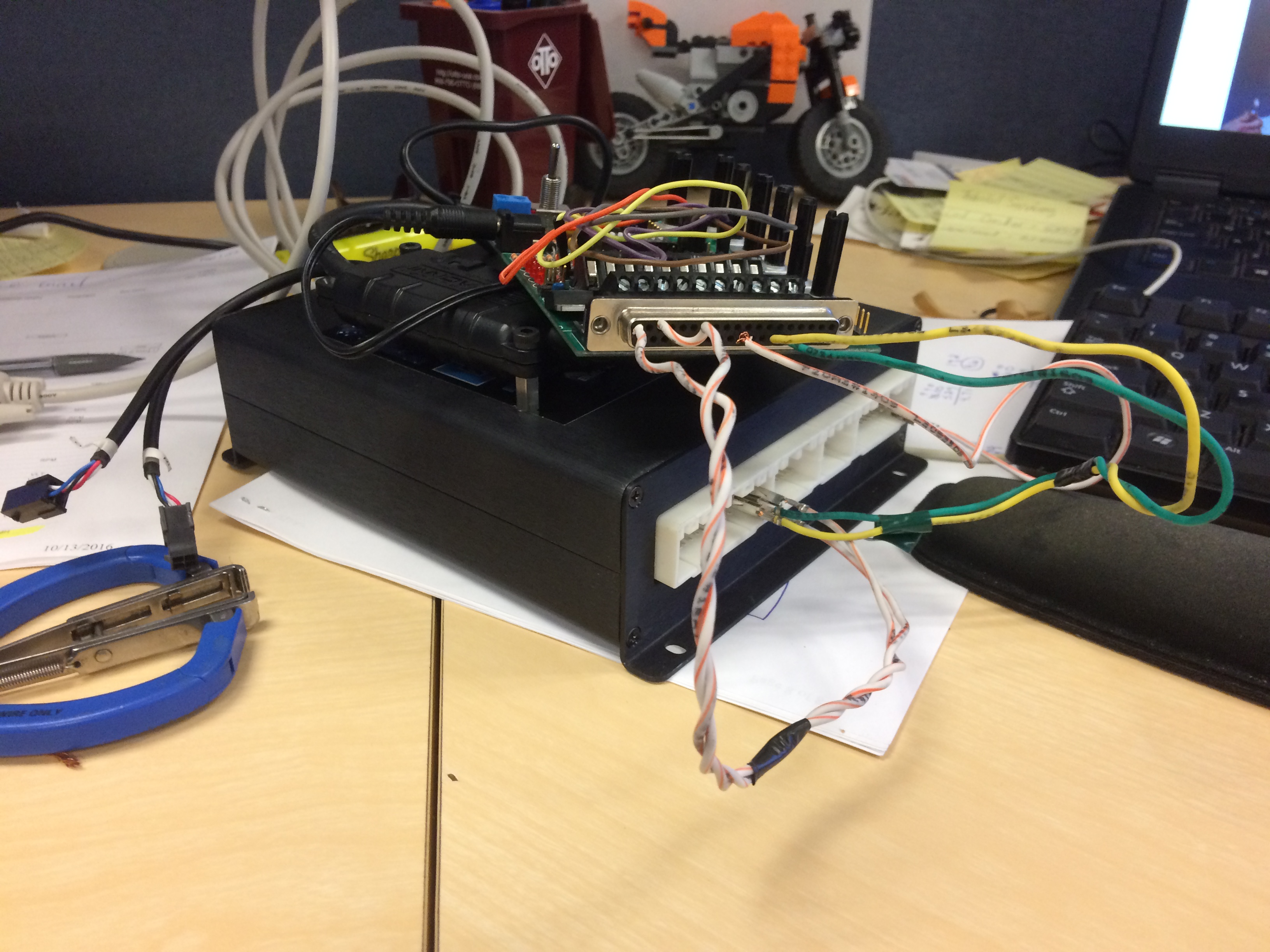
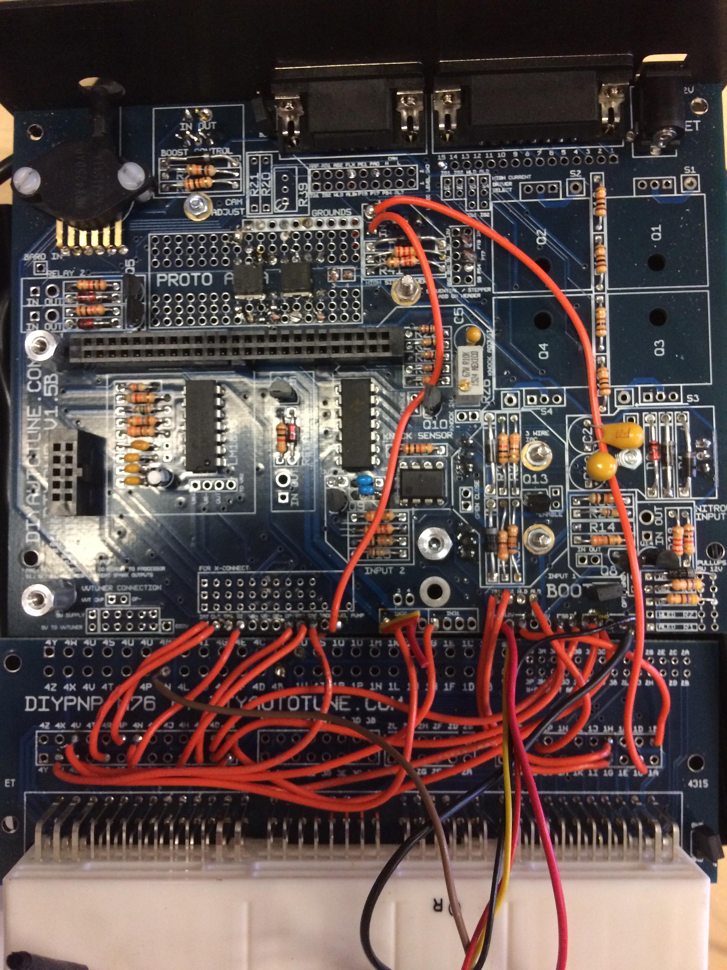
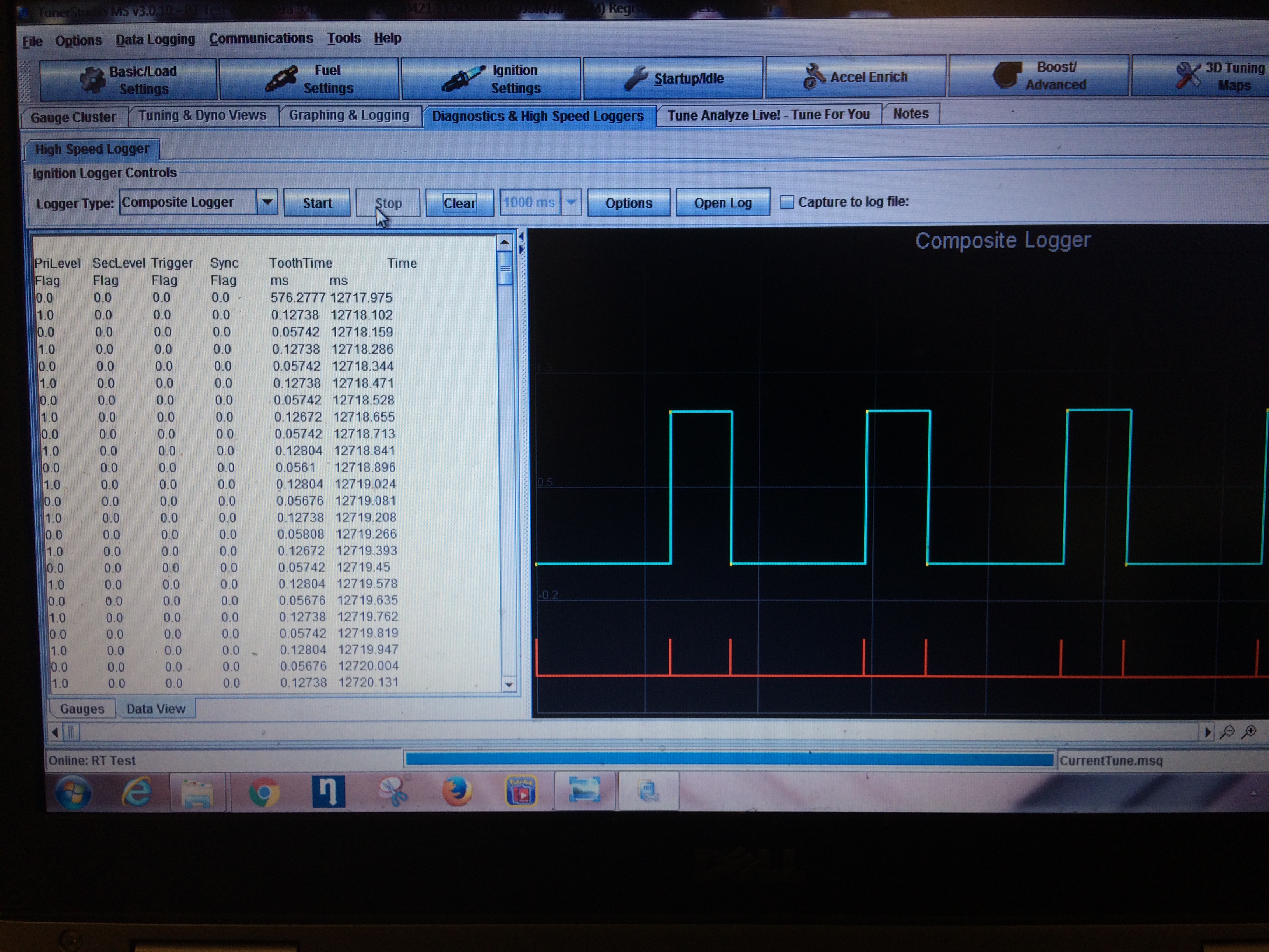
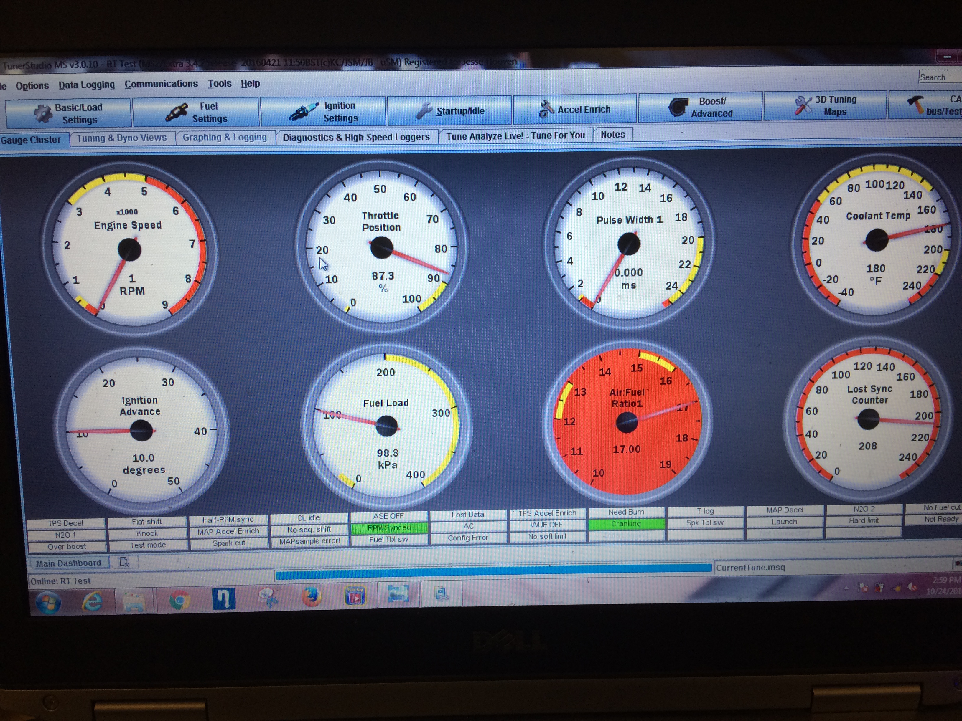
Below are pictures of what the ECU looks like and what tuner studio displays. after giving it rpm signal, it will stay at 1 rpm until you cycle the key. I think there is something simple and dumb wrong on the board but i am not sure. I have been looking for a schematic of the cam circuit on the board but cannot find one. Anyone know where i can get that info? Let me know if you have any thoughts on it.
loaded with firmware 3.4.2 and the 1.6 base map. untouched
symptoms first in car and then confirmed with a jim stim.
Below are pictures of what the ECU looks like and what tuner studio displays. after giving it rpm signal, it will stay at 1 rpm until you cycle the key. I think there is something simple and dumb wrong on the board but i am not sure. I have been looking for a schematic of the cam circuit on the board but cannot find one. Anyone know where i can get that info? Let me know if you have any thoughts on it.
Last edited by mmmjesse; 10-24-2016 at 03:03 PM.

Reply
 0
0

0

 10-25-2016, 04:43 PM
#6
Senior Member
Thread Starter
Join Date: Aug 2007
Posts: 574
Total Cats: 44
so i found out the problem with the JimStim. forgot a jumper. It now activates the tach in tuner studio without problems.
However, when i hook it up to my car, it still only shows 1 rpm. My car is a 93 that has run on a diypnp previously and is now on an ms3x with a bob. So two different cars show the same fault of 1rpm but the JimStim is able to work the tach fine.
However, when i hook it up to my car, it still only shows 1 rpm. My car is a 93 that has run on a diypnp previously and is now on an ms3x with a bob. So two different cars show the same fault of 1rpm but the JimStim is able to work the tach fine.
Reply
0
0
10-25-2016, 07:04 PM
#8
Senior Member
Thread Starter
Join Date: Aug 2007
Posts: 574
Total Cats: 44
to give a run down of how i have the jimstim connected.
1B- 28(12v)
4A- 1(GND)
4B- 4(GND)
4E- 24(OPT-)
4G- 25(VR2)
Then i did some testing to see if there is something that is shorting when the chassis connectors are hooked up.
I removed 1B and connected connector 1 on my car. When arranged like that the problem occurs. So that leads me to believe that there is something on the board that is shorted between VR2 and something that goes to connector one. So far i havent found any pins with real continuity to VR2.
Reply
0
0
 10-26-2016, 01:49 PM
#11
When you put the firmware on there, you did choose microsquirt, right?
Simple google search: https://www.miataturbo.net/megasquir...t-start-58398/
Simple google search: https://www.miataturbo.net/megasquir...t-start-58398/
Reply
1
1
10-26-2016, 02:07 PM
#12
Senior Member
Thread Starter
Join Date: Aug 2007
Posts: 574
Total Cats: 44
When you put the firmware on there, you did choose microsquirt, right?
Simple google search: https://www.miataturbo.net/megasquir...t-start-58398/
Simple google search: https://www.miataturbo.net/megasquir...t-start-58398/
I already read that thread and any other related thread i could find. Firmare is correct and has been reloaded multiple times to make sure. i have also tried multiple versions of the firmware.
Reply
0
0
10-26-2016, 03:12 PM
#15
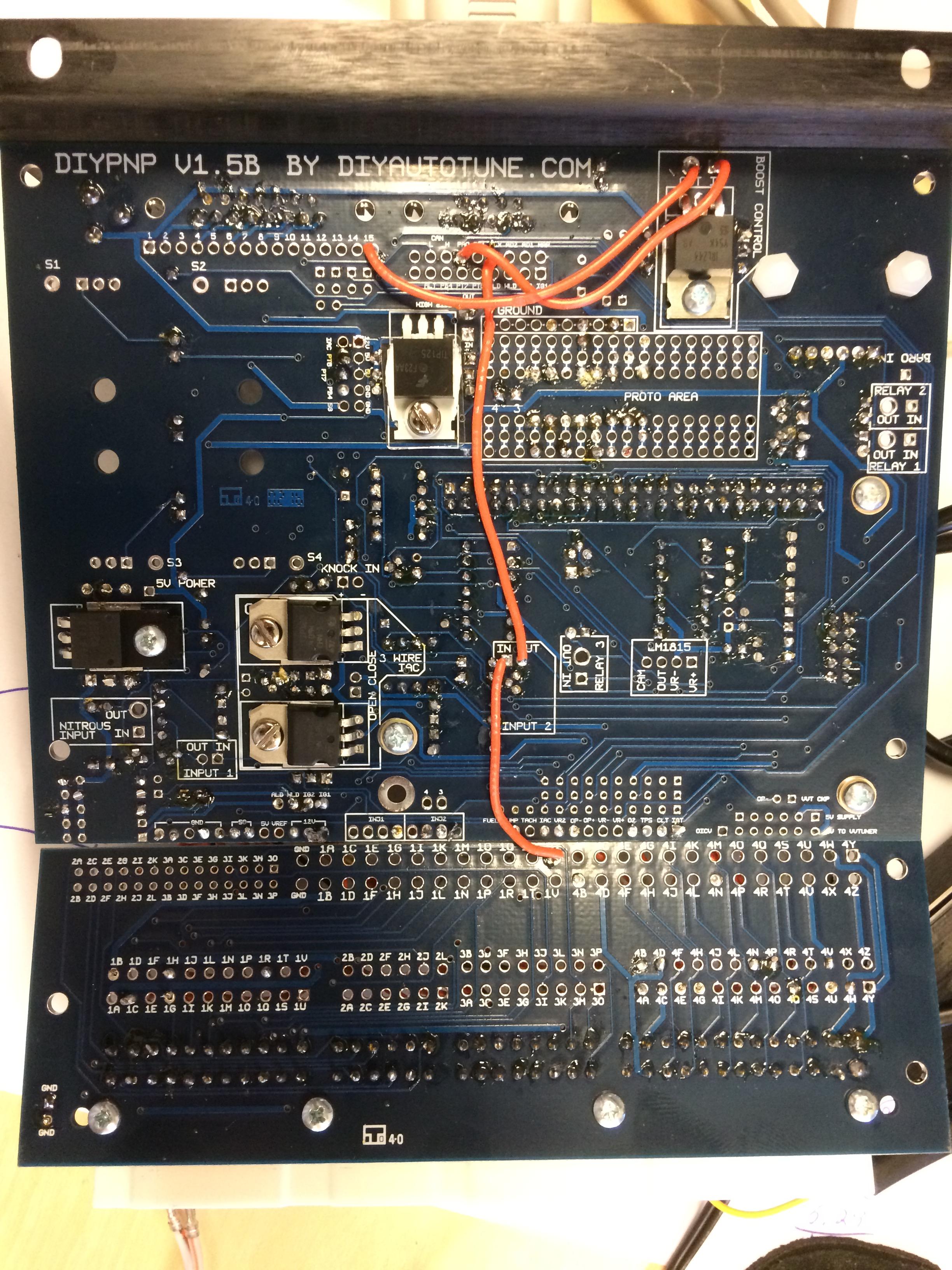
having built exactly one MS, I'm not going to be able to troubleshoot your specific issue, but I have soldered PCB's for a living. It's a little hard to judge based on the pics you posted, but it looks like you got a bunch of cold sockets. What soldering iron tip are you using? Do you have an adjustable temperature iron? I wouldn't be surprised if you built the thing right, but you have a cold joint that isn't conducting. You can touch up the board pretty easily. It looks to me like you did all your soldering from the underside of the board. Go back & touch up the tops of every joint that looks like it didn't flow well. Apply heat and more solder (mostly for the flux), but do it from the top of the board this time.
It's a bit of a long shot, but it's not going to hurt anything as long as you don't wayyy overheat anything.
It's a bit of a long shot, but it's not going to hurt anything as long as you don't wayyy overheat anything.
Reply
1
1
10-27-2016, 10:01 PM
#16
Senior Member
Thread Starter
Join Date: Aug 2007
Posts: 574
Total Cats: 44
having built exactly one MS, I'm not going to be able to troubleshoot your specific issue, but I have soldered PCB's for a living. It's a little hard to judge based on the pics you posted, but it looks like you got a bunch of cold sockets. What soldering iron tip are you using? Do you have an adjustable temperature iron? I wouldn't be surprised if you built the thing right, but you have a cold joint that isn't conducting. You can touch up the board pretty easily. It looks to me like you did all your soldering from the underside of the board. Go back & touch up the tops of every joint that looks like it didn't flow well. Apply heat and more solder (mostly for the flux), but do it from the top of the board this time.
It's a bit of a long shot, but it's not going to hurt anything as long as you don't wayyy overheat anything.
It's a bit of a long shot, but it's not going to hurt anything as long as you don't wayyy overheat anything.
I will put it in my car tomorrow and try again.
Reply
0
0
10-28-2016, 02:43 PM
#20
Senior Member
Thread Starter
Join Date: Aug 2007
Posts: 574
Total Cats: 44
Last night per Wackbards suggestion, i resoldered all connections from them top. I also removed the lc2 power and ground directly from the board. All works as it should now.
Has anyone else had a problem that was caused by wiring wideband power and ground straight to the board? I feel like it was just some bad soldering on the board that caused it. Thanks for all the help and cats to all.

Has anyone else had a problem that was caused by wiring wideband power and ground straight to the board? I feel like it was just some bad soldering on the board that caused it. Thanks for all the help and cats to all.
Reply
0
0


