Circuit and wiring gurus I need your help
 04-23-2011, 11:42 AM
#1

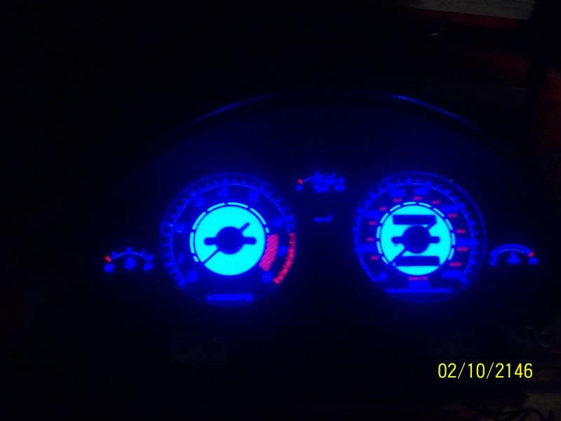
I installed a gauge cluster with an LED backlighting system. The only downsides is that there is an external on/off switch,a dn I want it to turn on and off with the headlight switch.
The on/off switch is a paper thin piece of plastic with a very thin spongy button that sort of pops in and then out when released. This goes to some sort of relay. Black box in picture below.
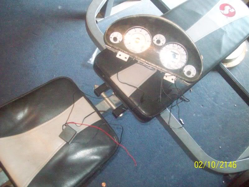
I have the hot wire hooked into the headlight switch power, so there is no way to activate the LED lights unless the headlights are on. I turn the headlights on, then press the pwr button for the LED lights and they come on. When on turn the headlights off, everything turns off because all power is cut (yay). I tried removing the on off switch and bridging the terminals and turning the power on; nothing happens, If I undo the bridge and make contact they turn on, touch the terminals again, and they turn off.
Does it sound like there is a way to get this circuit to turn on and off with headlight switch?
For your viewing pleasure:
The on/off switch is a paper thin piece of plastic with a very thin spongy button that sort of pops in and then out when released. This goes to some sort of relay. Black box in picture below.
I have the hot wire hooked into the headlight switch power, so there is no way to activate the LED lights unless the headlights are on. I turn the headlights on, then press the pwr button for the LED lights and they come on. When on turn the headlights off, everything turns off because all power is cut (yay). I tried removing the on off switch and bridging the terminals and turning the power on; nothing happens, If I undo the bridge and make contact they turn on, touch the terminals again, and they turn off.
Does it sound like there is a way to get this circuit to turn on and off with headlight switch?
For your viewing pleasure:

Reply
 0
0

0
04-23-2011, 12:20 PM
#2
Boost Pope


iTrader: (8)
Join Date: Sep 2005
Location: Chicago. (The less-murder part.)
Posts: 33,339
Total Cats: 6,793
Can you give us a link to the documentation for this kit? The easiest thing would be to figure out what voltage it's outputting to drive the LEDs, and then eliminate the black box and replace it with a constant-on regulator supplied by the general illumination circuit.
Reply
0
0
04-23-2011, 01:33 PM
#3
No documentation, bought it off here a week ago from someone that got it with a car. I could just put a voltmeter on it. I can get the voltage that is immediately coming out of the box. Then is it a matter of creating something that steps down the voltage from 12 to whatever the box outputs? What data would you need? current, voltage???
Reply
0
0
04-23-2011, 03:51 PM
#6
Boost Pope
iTrader: (8)
Join Date: Sep 2005
Location: Chicago. (The less-murder part.)
Posts: 33,339
Total Cats: 6,793
If you try to measure current by bridging across the two wires coming out of the controller, you will short circuit it. Current readings must always be taken in series, by interrupting the circuit and placing the meter inline with it.
Voltage readings, by comparison, are taken across the circuit (in parallel with it.) I'm more interested in voltage here, current would be more of a curiosity.
And yes, both of these can be done directly at the controller, or anywhere along the cable between it and the LEDs. You needn't touch the instrument cluster itself.
Reply
0
0

Thread
Thread Starter
Forum
Replies
Last Post
Zaphod
MEGAsquirt
47
10-26-2018 11:00 PM


