speed sensor in tranny, how many pulses per mile
 12-20-2011, 11:29 PM
#21

Description
The MAX9924–MAX9927 variable reluctance (VR or magnetic coil) sensor interface devices are ideal for position and speed sensing for automotive crankshafts, camshafts, transmission shafts, etc. These devices integrate a precision amplifier and comparator with selectable adaptive peak threshold and zero-crossing circuit blocks that generate robust output pulses even in the presence of substantial system noise or extremely weak VR signals.
The MAX9924–MAX9927 variable reluctance (VR or magnetic coil) sensor interface devices are ideal for position and speed sensing for automotive crankshafts, camshafts, transmission shafts, etc. These devices integrate a precision amplifier and comparator with selectable adaptive peak threshold and zero-crossing circuit blocks that generate robust output pulses even in the presence of substantial system noise or extremely weak VR signals.

Reply
 0
0

0
12-21-2011, 10:14 AM
#22

Oh my!
Numerical value =/= Term
61* Fahrenheit = 16* Celcius
Fahrenheit and Celcius are both (names and) terms representing temperature, whereas 61 =/= 16.
Roy and Joe, you are in violent agreement, your only discord is the relative value of your adopted term.
(And the goldfish tasted like chicken)
Numerical value =/= Term
61* Fahrenheit = 16* Celcius
Fahrenheit and Celcius are both (names and) terms representing temperature, whereas 61 =/= 16.
Roy and Joe, you are in violent agreement, your only discord is the relative value of your adopted term.
(And the goldfish tasted like chicken)
Reply
0
0
12-21-2011, 09:32 PM
#23
actually this thread has been very helpful to me, I am thinking of moving to a 3.6 r/p and was wondering how I was going to correct the speedo display
this thread has lead me to believe miata transmissions have an internal VR sensor feeding a counting circuit driving the speedo display; if that is the case all I have to do is adjust the counting circuit to recalibrate the speedo display;
I am sure I will be corrected if this is wrong; in fact, if this is wrong, please do tell me how to recalibrate the speedometer after changing for a different differential ratio
chicken huh, LOL
Reply
0
0
12-21-2011, 10:23 PM
#24
mkturbo.com


iTrader: (24)
Join Date: May 2006
Location: Charleston SC
Posts: 15,189
Total Cats: 1,685
actually this thread has been very helpful to me, I am thinking of moving to a 3.6 r/p and was wondering how I was going to correct the speedo display
this thread has lead me to believe miata transmissions have an internal VR sensor feeding a counting circuit driving the speedo display; if that is the case all I have to do is adjust the counting circuit to recalibrate the speedo display;
I am sure I will be corrected if this is wrong; in fact, if this is wrong, please do tell me how to recalibrate the speedometer after changing for a different differential ratio
chicken huh, LOL
this thread has lead me to believe miata transmissions have an internal VR sensor feeding a counting circuit driving the speedo display; if that is the case all I have to do is adjust the counting circuit to recalibrate the speedo display;
I am sure I will be corrected if this is wrong; in fact, if this is wrong, please do tell me how to recalibrate the speedometer after changing for a different differential ratio
chicken huh, LOL
To read the correct speed if you have a 3.6R&P you just need the correct speed sensor. I know they are out there, I am just not sure which one is which.
Reply
0
0
12-21-2011, 10:58 PM
#25

The na's use a mechanical speed sensor that goes to the gauge cluster, and then the gauge cluster outputs an electrical signal that MS can read.
To read the correct speed if you have a 3.6R&P you just need the correct speed sensor. I know they are out there, I am just not sure which one is which.
To read the correct speed if you have a 3.6R&P you just need the correct speed sensor. I know they are out there, I am just not sure which one is which.
For the gears I found this: You can choose an M502-17-441 (19 tooth) gear or an M503- (20 tooth) gear, it depends on what wheel/tire combo you are using. With my 205/50R15 my speedometer was barely off compared to the GPS.
1011-17-442A - This is the sleeve/housing that will position the gear in the proper location to engage the gear within the transmission. If the sleeve that comes in a 5-speed transmission is used, the smaller 6-speed gear will be free-floating and will not engage. Thus, no readings.
M502-17-441 - This is the actual gear.
9922-20-214 - Spring Pin for holding the gear in the sleeve.
9958-60-8166 - Oil Seal for inside the sleeve.
1011-17-443 - O-Ring for the outside of the sleeve.
The above may or may not be actually useful

Reply
0
0
12-21-2011, 11:12 PM
#26
Boost Pope

iTrader: (8)
Join Date: Sep 2005
Location: Chicago. (The less-murder part.)
Posts: 33,339
Total Cats: 6,793
In some NAs (1.6 cars without either cruise or an automatic transmission for sure, possible others), the wire which is supposed to leave the instrument cluster carrying this signal is absent. Later cars may or may not have the wire in place- you'll have to check.
Easiest way to find out is to pop the hood over the instrument cluster and look for a grn/red wire at terminal 2F:
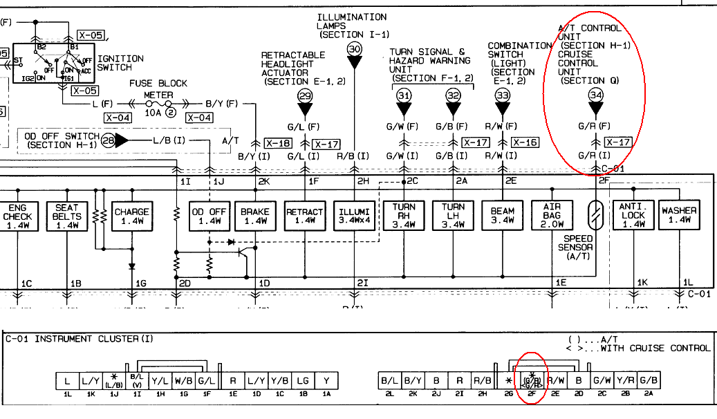
If you don't have the wire, you can run one directly to the terminal on the back of the speedo. I posted a picture of this years ago in the Emanage forum, too lazy to look for it.
The switch is a closure to ground, so you'll need a pullup if you have an early car with no A/T or cruise. Test the wire first- it may already have voltage on it (test it while moving slowly, so ensure that you cycle the switch on and off) in which case no pullup is required.
Reply
0
0
12-22-2011, 03:45 AM
#27
no I haven't searched [yet] cause I am not ready to pull the trigger on the r/p swap
[and I did not even know about a sub-forum called emanage]
yes my trans is the stock 94, and since my car is an M, it does have cruise
thanks for the pin out, most helpful to us males with defective color preception
[and I did not even know about a sub-forum called emanage]
yes my trans is the stock 94, and since my car is an M, it does have cruise
thanks for the pin out, most helpful to us males with defective color preception
Reply
0
0
12-22-2011, 01:51 PM
#29
mkturbo.com
iTrader: (24)
Join Date: May 2006
Location: Charleston SC
Posts: 15,189
Total Cats: 1,685
I will check out my 94's wiring tonight to verify what joe posted. VSS has been working well enough in my car, just has a problem with calculating the correct gear for lower ones.
Reply
0
0
12-22-2011, 02:45 PM
#31
Boost Pope
iTrader: (8)
Join Date: Sep 2005
Location: Chicago. (The less-murder part.)
Posts: 33,339
Total Cats: 6,793
The VSS signal, be it from an NB-style sensor or an NA-style speedometer, is taken from the tailshaft of the transmission (after the main gearing) and is thus accurate regardless of what gear you are in. It would work for a car rolling down a hill in neutral with the engine off.
Yes. I had this wired to the EMU in my '92 many years ago. It's how I know I was doing precisely 104 MPH when the cop pulled me over in a 55 MPH zone.
Reply
0
0
12-22-2011, 03:01 PM
#32
mkturbo.com
iTrader: (24)
Join Date: May 2006
Location: Charleston SC
Posts: 15,189
Total Cats: 1,685
Huh?
The VSS signal, be it from an NB-style sensor or an NA-style speedometer, is taken from the tailshaft of the transmission (after the main gearing) and is thus accurate regardless of what gear you are in. It would work for a car rolling down a hill in neutral with the engine off.
The VSS signal, be it from an NB-style sensor or an NA-style speedometer, is taken from the tailshaft of the transmission (after the main gearing) and is thus accurate regardless of what gear you are in. It would work for a car rolling down a hill in neutral with the engine off.
Reply
0
0
12-24-2011, 05:36 PM
#35
Senior Member
Thread Starter

Join Date: Nov 2007
Location: Belgium
Posts: 999
Total Cats: 73
Thanks for the info guys. So we have a VR sensor that outputs a 8200 ppm AC signal.
To convert this to a 0-5V DC signal for the MS, I can copy the stock VR circuit from the V3.0 board, a LM1815 based circuit or the Maxim 9924 based circuit (but those are too difficult to use). Will try to get the LM1815 circuit in the proto area.
My S2000 cluster expects 156K, so I'll first have to multiply the input frequency by 19, unless the MS output can do this.
Last edited by WestfieldMX5; 12-24-2011 at 07:04 PM.
Reply
0
0
01-03-2012, 04:18 AM
#36
Most speedometers are square wave and read off the leading edge of the square. The pulse is generated by a reluctor as a permanent magnet passes. As Joe mentioned earlier in the post, the easiest way to check the pulses is to check the reading when the car is moving. A dyno can be a helpful tool for this as well.
Reply
0
0
01-05-2012, 12:13 PM
#37
Tour de Franzia
iTrader: (6)
Join Date: Jun 2006
Location: Republic of Dallas
Posts: 29,085
Total Cats: 375
Most speedometers are square wave and read off the leading edge of the square. The pulse is generated by a reluctor as a permanent magnet passes. As Joe mentioned earlier in the post, the easiest way to check the pulses is to check the reading when the car is moving. A dyno can be a helpful tool for this as well.
Reply
0
0
01-06-2012, 01:29 AM
#38
Only on motorcycles, sorry. I was looking for a picture of the mini-oscilliscope I used, but I must not have kept the pictures. However, I do have some reference numbers for a Honda:
180mph = 3.02 KHz
119mph = 2.00 KHz
59mph = 1.00 KHz
3mph = 50 Hz
The minimum voltage required to trigger the reluctor was 3.85V p+p, and normally ran on 5V.
Interesting; the odometer was clocking the miles while I tested the speedometer readings. Also, since standard speedometers don't show tenths of a mile, a set mph on the speedometer would be shown within a range of Hz readings. Hope this helps.
Reply
0
0
02-12-2012, 04:25 PM
#39
Senior Member
Thread Starter
Join Date: Nov 2007
Location: Belgium
Posts: 999
Total Cats: 73
Turns out the signal is 4800ppm, not 8200ppm and the S2000 cluster expects 156K thus 32.5 times faster.
I'm using a 32 multiplier which is close enough. The stock speedo reads a bit high anyway so it'll be spot on. If I get it working that is.
I'm using a 32 multiplier which is close enough. The stock speedo reads a bit high anyway so it'll be spot on. If I get it working that is.
Reply
0
0


