recomend a 1 3/4" water temp gague
#1
Thread Starter
Elite Member
iTrader: (7)
Joined: May 2007
Posts: 3,006
Total Cats: 103
From: Dallas, Tx
while my dash is out i'm going to switch the gages in the cluster for a real one. can anyone recommend one that looks like 99 oem, so black face and green lights are a big plus.
#2
Not sure how the innards of an NB cluster compare to an NA, but I used VDO Visions in mine.
http://picasaweb.google.com/cscarpulla/miatagauges#

C
http://picasaweb.google.com/cscarpulla/miatagauges#

C
#8
I don't know which site you're looking at, but I bought them from eguages.com
This isn't a 'drop in' procedure, you need to mod the innards of the cluster. Did you look at the pics in the link I posted?
http://picasaweb.google.com/cscarpulla/miatagauges#
C
This isn't a 'drop in' procedure, you need to mod the innards of the cluster. Did you look at the pics in the link I posted?
http://picasaweb.google.com/cscarpulla/miatagauges#
C
#9
Thread Starter
Elite Member
iTrader: (7)
Joined: May 2007
Posts: 3,006
Total Cats: 103
From: Dallas, Tx
looking into ways to change my gauges cluster to blue back lighting seeing as i can only find 1 green light water temp gauge with a black face.
Last edited by jeff_man; 05-27-2010 at 05:05 AM.
#10
I don't know which site you're looking at, but I bought them from eguages.com
This isn't a 'drop in' procedure, you need to mod the innards of the cluster. Did you look at the pics in the link I posted?
http://picasaweb.google.com/cscarpulla/miatagauges#
C
This isn't a 'drop in' procedure, you need to mod the innards of the cluster. Did you look at the pics in the link I posted?
http://picasaweb.google.com/cscarpulla/miatagauges#
C
The cutting of plastic is easy.
The circut board on the back scares me. What did you have to do with that? Any electrical bits you needed to cut into/move/anything?
#11
I don't have any completed pics of the back of that cluster, but I probably had to solder in a few jumpers. It's not rocket science though, you just need to follow the traces visually, and replace the ones you cut out. You'll also want to wire the bulb from the aftermarket gauge into the same circuit as the cluster bulbs, but again, the traces are right there to see.
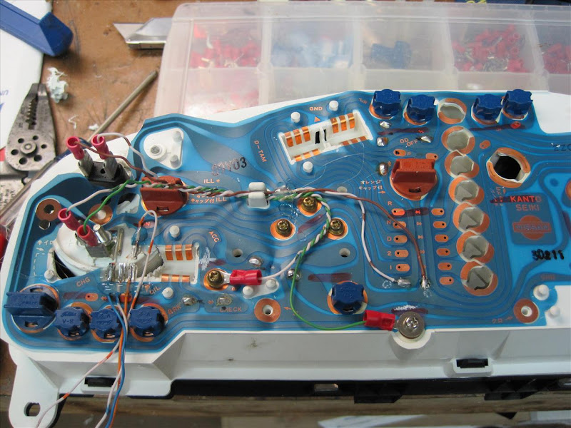
Here's the back side of an SE-R cluster I did for a buddy of mine. It allot more work than the Miata cluster, because you need to chop out part of the socket in the lower left hand corner.

Here's the back side of an SE-R cluster I did for a buddy of mine. It allot more work than the Miata cluster, because you need to chop out part of the socket in the lower left hand corner.

#13
It's a flexible circuit board. The lines are the circuits. Most of each circuit is covered with a non-conductive material, and the areas left uncovered are copper colored. If you aren't proficient at soldering, this may not be a good mod to undertake, as it's tricky to solder without burning a hole through the plastic.
C
C
#14
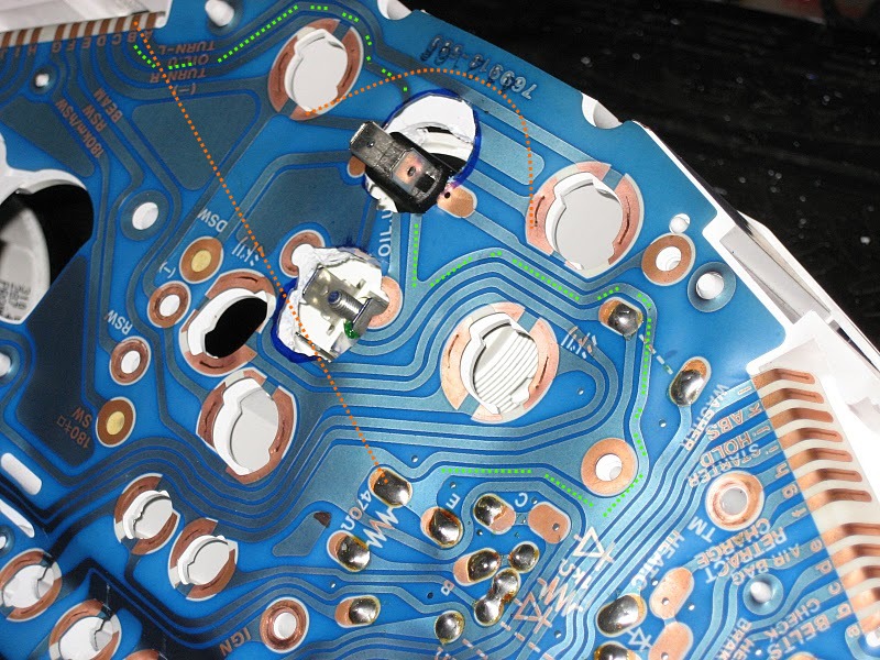
Follow the dotted green line from the upper left side of the picture line to where I cut the circuit out to make room for the bulb, and beyond to the solder pad. This is a convient place to solder a replacement wire to (as indicated by the dotted orange line). If there was no exposed solder pad, or bare copper, I would have scraped some of the blue coating off to expose the copper below it.
[edit]Same theory for the circuit between the two bulb sockets.[/edit]

#15
Here's the thing, you don't really need to know where they go. You just need to replace whatever you've cut out.
Follow the dotted green line from the upper left side of the picture line to where I cut the circuit out to make room for the bulb, and beyond to the solder pad. This is a convient place to solder a replacement wire to (as indicated by the dotted orange line). If there was no exposed solder pad, or bare copper, I would have scraped some of the blue coating off to expose the copper below it.

Follow the dotted green line from the upper left side of the picture line to where I cut the circuit out to make room for the bulb, and beyond to the solder pad. This is a convient place to solder a replacement wire to (as indicated by the dotted orange line). If there was no exposed solder pad, or bare copper, I would have scraped some of the blue coating off to expose the copper below it.


#19
The easy answer, unless you're smart enough to figure out otherwise, replace everything that you cut out. Just get your game plan finished BEFORE cutting.
And hot glue works nicely for tacking wires down. You can see where I used it on the back of the SE-R cluster in post #11
C
And hot glue works nicely for tacking wires down. You can see where I used it on the back of the SE-R cluster in post #11
C

Thank you again.
Thread
Thread Starter
Forum
Replies
Last Post


