When you click on links to various merchants on this site and make a purchase, this can result in this site earning a commission. Affiliate programs and affiliations include, but are not limited to, the eBay Partner Network.
Lets Discuss: Charging Indicator and It's Necessity for Charging System
Hey all.
Working on getting my aftermarket dash situated in my NA miata, having completely removed the outgoing stock cluster. One point of interest I've had is the necessity of the Charging indicator bulb in the OEM cluster.
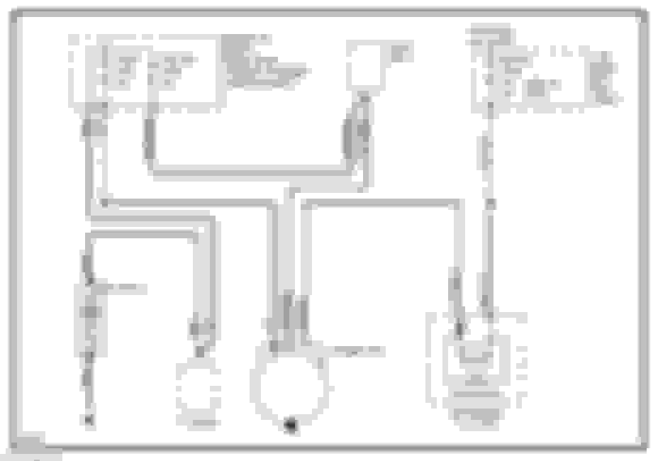
When I first removed the cluster, I didn't have any ramifications from doing so. In fact, I didn't even process the charging indicator could be actually relevant to charging system performance; I took it as a feedback only circuit. However, a bit down the road, I had an issue where my alternator would not "turn on" on engine fire. If I manually excited the 2 pin connector on the alternator, it would start charging until the car was turned off, and the cycle would repeat. This is when I started looking into the necessity of the bulb. See the diagram below. Trace "1G" from the Indicator feeds to one of the alternator pins, and is the only source of relative voltage to the alt.
That being said, after tinkering with it some more, I'm now back in my ORIGINAL spot, where no bulb or external excitation is connected, and everything seems to work just fine. As I go to finalize my dash layout, I'm debating if I NEED to plan for an aftermarket charging indicator incandescent bulb to mimic the OEM. Anyone have any experience on the topic or insight otherwise? Appreciate it!
If you've already had intermittent issues with charging, and those issues were fixed by giving 12V to the indicator pin, why not just add a resistor to 12V to mimic the bulb?
If you've already had intermittent issues with charging, and those issues were fixed by giving 12V to the indicator pin, why not just add a resistor to 12V to mimic the bulb?
If they were consistent, I'd be more convinced. As of now, I don't have to add anything, and it will charge on its own. The W/B wire on the alt is *open* right now with no apparent issue. My theory is that initial startup RPM is enough to self excite the internal regulator. But without knowing a functional description of how these alternators were designed, or exactly what they expect in what functional mode, I'm shooting in the dark a bit.
I'm not opposed to adding a resisted 12V line to the circuit, but want to understand what and WHY I'm doing so. Ya know?
What year is the ECU and alternator?
In the NB models the ECU evaluates the voltages, and triggers the alternator.
In earlier cars the circuits you are asking about do that job.
So if it is an NB, then the bulb is just an indicator, and I don't believe will matter.
If it is an NA, then the indicator in the dash plays both an information and a control role.
There is a comparator circuit inside the older alternator that evaluates the alternator output voltage versus the voltage going to the pin on the dashboard system. When the dash pin is lower in V then current flows though the bulb indicator, and the internal comparator circuit causes the alternator to generate more current.
You can run these systems without the light bulb, but you need to connect both leads to the original voltage sources they were originating from.
Note that the brighter the indicator bulb glows, the more current flowing in it, so the more voltage drop across it, and the bigger the signal the comparator sees. So replacing the bulb with a resistor that can carry some amps, and has about the same resistance as the bulb, seems like the safest way to get the same function as Mazda planned for. You will see in the circuit shown that there was also a diode.
I have tried to attach a pdf file from Ford, for the 1.6 L turbo Capri, and 1.3 L Festiva. Both use the Mazda engine and alternator design used in the NA Miata. Note the comment never to run without the two control leads connected.
There are other ways you can deal with this, such as adding a diode to the two wire connector circuit, but I don't know the details.
A few more clarifications came to mind after my post above. Your circuit diagram of the dashboard system shows a diode, a bulb and a resistor in parallel with the bulb.
The diode ensures a 0.6 V drop from battery voltage across the diode, so the lead to the alternator is at least 0.6 V lower than the lead from the battery/alternator output, to the other terminal, whenever there is any current flowing in the circuit, but independent of the current.
The resistor and lamp in parallel give a net resistive load that will also consume battery voltage, but this is current dependent.
To duplicate this effect you need a diode in series with a resistor, and the resistor should have a value that is the parallel combination of the resistor in the instrument cluster and the bulb.
The bulb will be a 12 V bulb (well ... yeah, sorry), and may also have a current stamped on it, so you can calculate the resistance. But I do not know where you would find the R in the cluster. It may not be in isolation in the cluster, so measuring it may not be easy.
I would be inclined to go see a local alternator repair shop with that diagram, and ask them how to make an appropriate replacement for the cluster, or if you can get away with something more simple.
This has been discussed before - the alternator is self exciting, you can run without a dash and the charging system works - both NA and NB. The only difference (in my experience) is V8 swaps, where the GM alternator needs to have the diode in the dash shorted/bypassed to work correctly as an excitor with a pre-pwm controlled old style LS1 alternator (not LFX).
 01-24-2020, 10:12 AM


 0
0


