How do high output alternators work?
 02-18-2016, 09:22 PM
#1
Junior Member
Thread Starter
iTrader: (1)

Join Date: Jan 2016
Location: Los Angeles
Posts: 179
Total Cats: 29
I've read threads on here about using higher output alternators and when my factory alternator started struggling I brought it to a shop and had it rewound for more current. It works great now and is rated for a maximum of 140 amps rather than 70. Most importantly it powers my giant Spal fans without any voltage dips and dimming headlights at idle. Very satisfied, but I didn't really have any idea what I paid the shop to do and why it worked. I had also read reports about some high output alternators being worse than OEM at idle and I wanted to understand why mine was different.
In case anyone else is curious, I found a great free textbook reference on car alternators:
http://cdn.intechopen.com/pdfs/38166...lternators.pdf
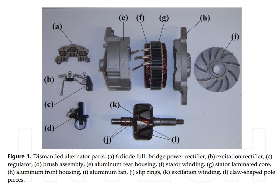
Here are all the components of the Lundell alternator used in cars:
Obviously more current is generated the faster the alternator spins. The shape of the current generation curve is determined by the number of turns in the stator winding. Counterintuitively, fewer turns in the winding produces a higher maximum output, but with the cost of a reduced current output at lower alternator rpms.
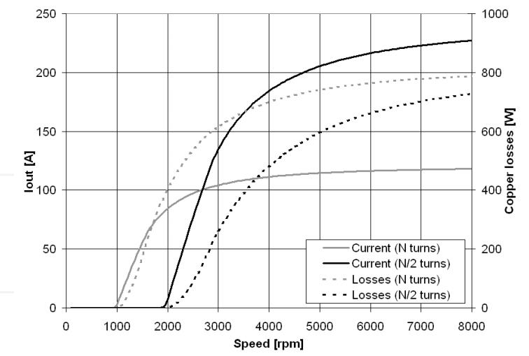
So when you have your alternator rewound, they're typically reducing the number of turns in the stator. That explains why some brands of HO alternator produce less current at idle than the OEM units. In order to compensate for the lower output at engine idle a common technique is to use a smaller pulley to increase the alternator rpm for a given engine speed. This is what my shop did. However, this can result in greater mechanical wear and reduces the efficiency -- for every hp going to spinning the alternator you get fewer amps back the higher the rpm goes.
Also, more claw poles ('l' in the diagram) can be added to increase output, but this has a similar reduction in efficiency. From what I understand that is typically how alternators are designed for trucks and larger vehicles.
If you're looking to have an alternator rewound for more amps, I recommend asking the shop what they will do to improve output at idle.
In case anyone else is curious, I found a great free textbook reference on car alternators:
http://cdn.intechopen.com/pdfs/38166...lternators.pdf
Here are all the components of the Lundell alternator used in cars:
Obviously more current is generated the faster the alternator spins. The shape of the current generation curve is determined by the number of turns in the stator winding. Counterintuitively, fewer turns in the winding produces a higher maximum output, but with the cost of a reduced current output at lower alternator rpms.
So when you have your alternator rewound, they're typically reducing the number of turns in the stator. That explains why some brands of HO alternator produce less current at idle than the OEM units. In order to compensate for the lower output at engine idle a common technique is to use a smaller pulley to increase the alternator rpm for a given engine speed. This is what my shop did. However, this can result in greater mechanical wear and reduces the efficiency -- for every hp going to spinning the alternator you get fewer amps back the higher the rpm goes.
Also, more claw poles ('l' in the diagram) can be added to increase output, but this has a similar reduction in efficiency. From what I understand that is typically how alternators are designed for trucks and larger vehicles.
If you're looking to have an alternator rewound for more amps, I recommend asking the shop what they will do to improve output at idle.

Reply
 1
1

1
02-19-2016, 09:12 AM
#2
Someone correct me if I'm wrong;
Reducing the number of windings is kind of like shifting to a lower gear in a transmission. The car has a lot more torque (more amps), but has a lower top speed (less volts). Unfortunately, voltage is tied to alternator speed. A stock alternator is mechanically designed to carry the standard voltage load at idle, and as speed increases so does the mechanical voltage output of the alternator. The alternator voltage is then governed by either the ECU or alternator electronics so that it has a max output and doesn't **** up your electronics. When the design is altered so that your current is higher, then it must spin faster to produce the initial voltage, resulting in low voltage idle conditions - it doesn't matter how many amps your alternator produces if it isn't carrying enough volts.
If you buy a high current alternator, I suspect it will be physically larger and more difficult for the engine to turn in order to have both the correct idle voltage and the higher output amperage. (Kind of like putting a bigger engine in the car to increase the torque instead of shifting gears.)
Reply
1
1
02-19-2016, 11:08 AM
#3
Elite Member

Join Date: Jul 2005
Posts: 6,420
Total Cats: 84
Good article, and seems accurate to me.
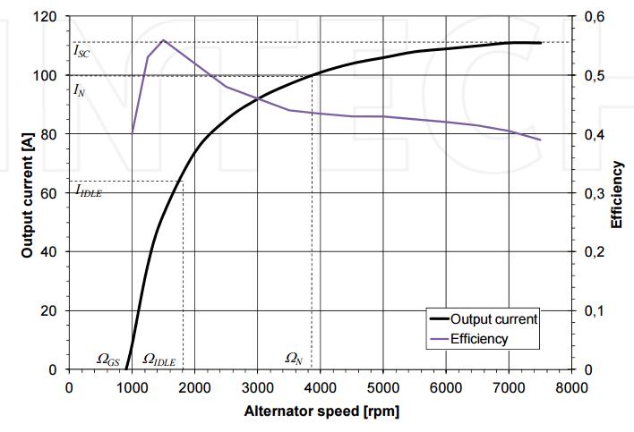
As an aside, a peak efficiency of 55% is pathetic. The variable speed nature of the application makes it more difficult to achieve high efficiency at a broad range of speeds.
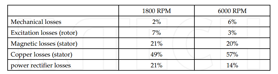
I didn't know that most of the losses were in the stator windings. In this case, adding space for thicker, Litz (multistrand) windings will help.
Industrial variable speed induction motors regularly achieve 90+% peak efficiency. The Tesla cars achieve this, IIRC. Induction alternators can be made but require complex electronics (compared to the rectifier in regular slip-ring alternators). BTW most electric cars on the road use permanent magnet motors, which have significantly lower cruising efficiency.
This is part of the reason Tesla get more range out of their cars. I interviewed at a startup BTW that has patents on very high power density, very efficient EV motors. 300 hp out of a motor that's about 18" long and 14" diameter!
The reason many OEs still use PM instead of more efficient induction motors is their stodginess. Most EVs still use a 12V lead-acid batteries, even thought they have a ginormous traction battery in the back! Did I mention they were stodgy? In such EV's the alternator is replaced by a DCDC converter with about 98% efficiency.
To put power conversion efficiencies in perspective, I'm designing a 3 kW DCDC converter that needs to hit almost 99% efficiency... obviously electrical converters will be more efficient than electrical -> mechanical or vice versa.
In a car with high MPG the alternator can be a significant loss. The nerds at ecomodder.com find that running a large battery with no alternator showed significant MPG improvements.
And of couse the OEs like Bosch now have had high efficiency alternators for a while now. Efficiencies are closer to 70%:
Bosch launches new high-efficiency alternator range - SAE International
As an aside, a peak efficiency of 55% is pathetic. The variable speed nature of the application makes it more difficult to achieve high efficiency at a broad range of speeds.
I didn't know that most of the losses were in the stator windings. In this case, adding space for thicker, Litz (multistrand) windings will help.
Industrial variable speed induction motors regularly achieve 90+% peak efficiency. The Tesla cars achieve this, IIRC. Induction alternators can be made but require complex electronics (compared to the rectifier in regular slip-ring alternators). BTW most electric cars on the road use permanent magnet motors, which have significantly lower cruising efficiency.
This is part of the reason Tesla get more range out of their cars. I interviewed at a startup BTW that has patents on very high power density, very efficient EV motors. 300 hp out of a motor that's about 18" long and 14" diameter!
The reason many OEs still use PM instead of more efficient induction motors is their stodginess. Most EVs still use a 12V lead-acid batteries, even thought they have a ginormous traction battery in the back! Did I mention they were stodgy? In such EV's the alternator is replaced by a DCDC converter with about 98% efficiency.
To put power conversion efficiencies in perspective, I'm designing a 3 kW DCDC converter that needs to hit almost 99% efficiency... obviously electrical converters will be more efficient than electrical -> mechanical or vice versa.
In a car with high MPG the alternator can be a significant loss. The nerds at ecomodder.com find that running a large battery with no alternator showed significant MPG improvements.
And of couse the OEs like Bosch now have had high efficiency alternators for a while now. Efficiencies are closer to 70%:
Bosch launches new high-efficiency alternator range - SAE International
Reply
1
1
 02-19-2016, 11:50 AM
#6
Boost Pope


iTrader: (8)
Join Date: Sep 2005
Location: Chicago. (The less-murder part.)
Posts: 33,339
Total Cats: 6,793
The voltage is adjusted by varying the intensity of the field winding. On older alternators this is done internally, and on newer alternators it's done by the ECU.
The amount of current (amperage) drawn from the alternator is simply a mathematical function of the voltage being produced by it relative to the equivalent resistance of the load connected to it. Specifically, I = V/R, where I is current, V is source voltage, and R is load resistance.
The only way to artificially decrease the current coming out of the alternator is to reduce its voltage, but of course doing that defeats the point of having an alternator in the first place. If you decrease the alternator's voltage to below the float voltage of the battery, then the battery will start to discharge and eventually go flat.
In theory, a CVT-style transmission could be engineered to maintain the alternator at a constant speed, however the mechanical losses in the transmission would outweigh the very small efficiency gain at the alternator. If we assume a typical continuous alternator load to be around 40 amps (which is probably high) and voltage to be around 14 volts (which is a good median average), then going from 40% efficiency to 55% efficiency saves you around 380 watts of mechanical power, which is around 0.5 HP.
Reply
0
0
 02-21-2016, 02:52 AM
#9
Junior Member
Thread Starter
iTrader: (1)
Join Date: Jan 2016
Location: Los Angeles
Posts: 179
Total Cats: 29
I left all the OEM wiring in place for redundency. I ran 1/0 gauge wire as follows:
Positive:
battery to starter
starter to distribution block
distribution block to an auxillary fuse panel that I bought
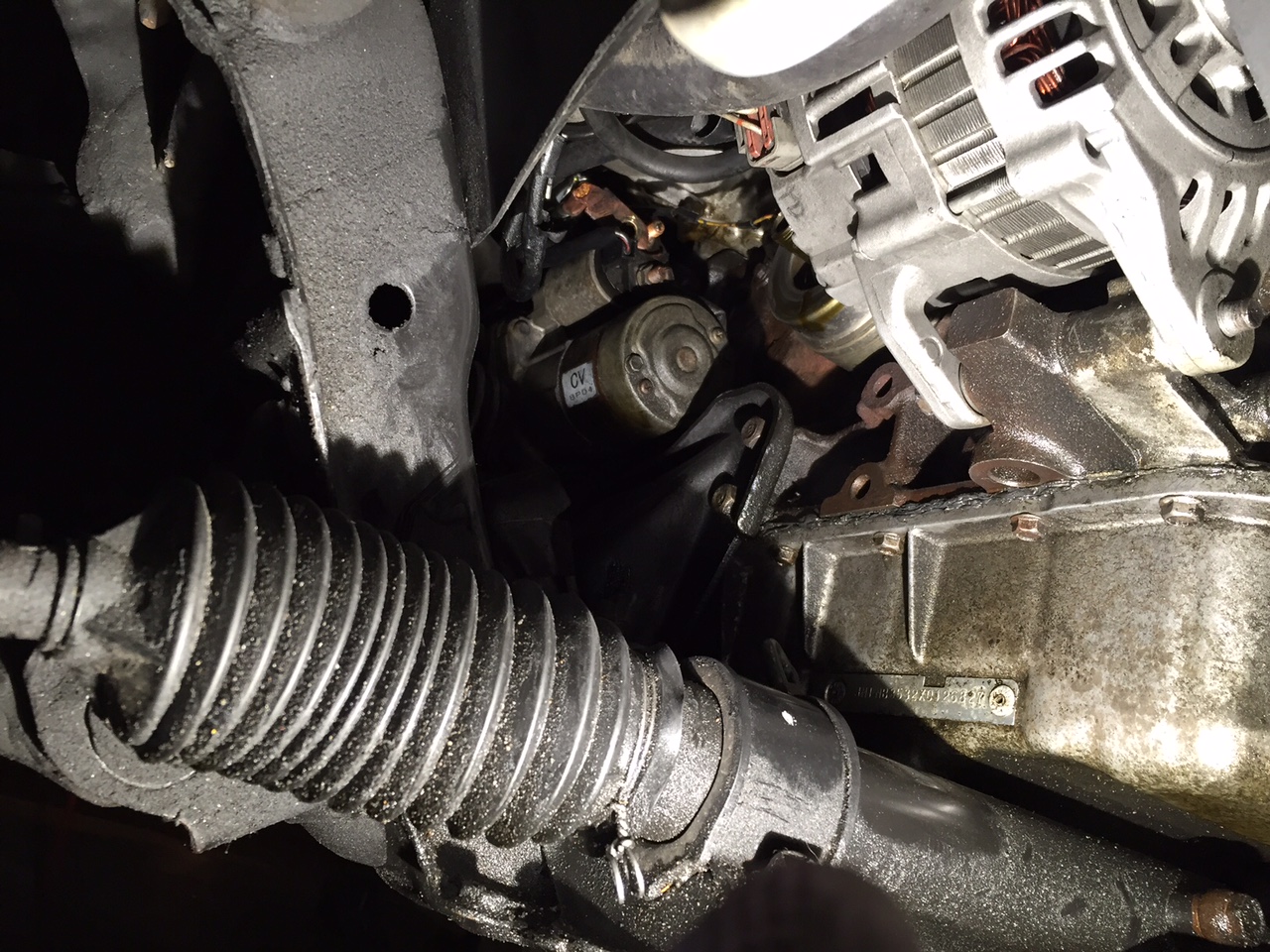
distribution block to alternator
Negative:
battery to chasis (trunk wall)
battery to power plant frame
alternator case to chasis
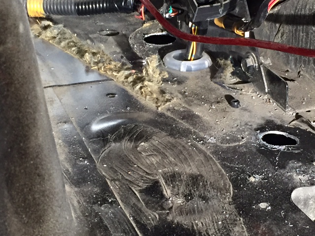
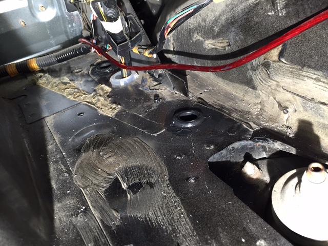
Some pictures:
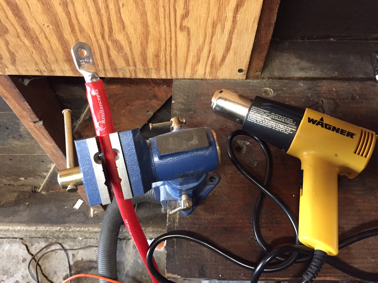
There were already two holes from the factory (thanks Mazda!) in the passenger side trunk tunnel. I just had to bore them out a bit to get the fat wire to fit.
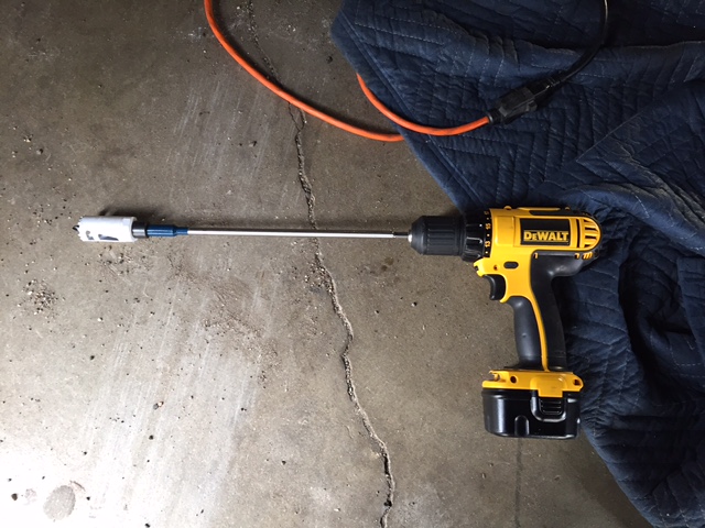
The closer hole required a 90 degree drill adapter, they're pretty cheap on Amazon and come in handy now and then. I bored out the hole closer to the front of the car from the bottom with a drill extension and a hole saw.
I put some rubber grommets on the holes and smeared Permatex in order to keep moisture out.
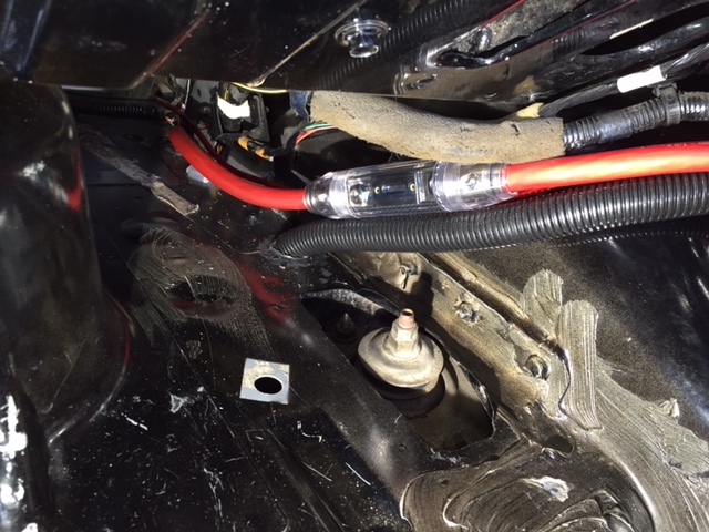
300 amp fuse on the positive wire to the starter.
I also added a 150 amp fuse to the OEM positive wire. I felt this was necessary because it connected with my wires at the starter, so if anything went wrong with mine and the 300 amp fuse blew current could still flow unrestricted throught the OEM cable.
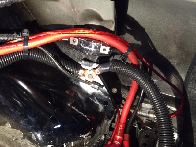
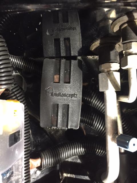
Here is the fused distribution block
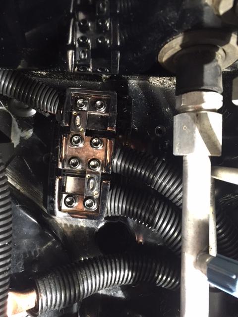
There is a 150 amp fuse connecting the alternator to the starter/battery, and another 100 amp fuse connecting the starter/battery to the auxillary fuse panel.
I relocated my windshield washer fluid bottle and used the bracket to mount the second panel:

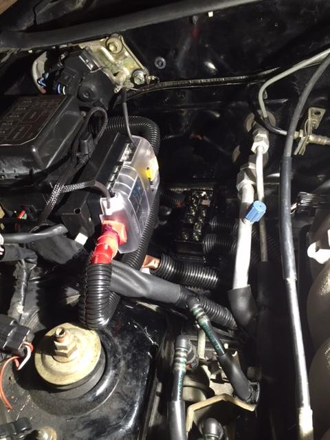
Cover to protect the distribution block
Right now I only have my HIDs connected to the secondary fuse panel, but I'm excited to add more gadgets. It will be very nice to have a go-to place to tap +12V and have all my fuses in one location for things like a larger horn or LED lights.
Fair warning: Not very experienced, all this might be really dumb.
Last edited by tenthe; 02-21-2016 at 04:45 AM.
Reply
1
1
02-21-2016, 03:28 PM
#10
Elite Member
Join Date: Jul 2005
Posts: 6,420
Total Cats: 84
That's a lot of work.
For anyone who is thinking of upgrading the alternator to run heavy loads, you can simply add fused wires from said new large loads (e.g. Spals), directly to the new alternator and leave the rest of the car's wiring alone.
For anyone who is thinking of upgrading the alternator to run heavy loads, you can simply add fused wires from said new large loads (e.g. Spals), directly to the new alternator and leave the rest of the car's wiring alone.
Reply
1
1
02-21-2016, 03:48 PM
#12
Junior Member
Thread Starter
iTrader: (1)
Join Date: Jan 2016
Location: Los Angeles
Posts: 179
Total Cats: 29
949 Racing Emilio
Reply
0
0

Thread
Thread Starter
Forum
Replies
Last Post


